 In the following section we'll describe the various building blocks that comprise a wireless sensor [don't worry...there aren't too many]. You will only need to connect a few basic wires to get your first sensor up and running...

The "brain"
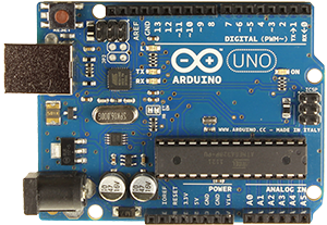
We've chosen the Arduino board for the brainy part in the sensor. There are a few reasons why:
- It is easy to program - we provide ready-to-download examples for you.
- It has a lot of input/output connections - for your sensors.
- The hardware is open source - so there are plenty inexpensive clones available.
- Low power consumption - sensors can optionally run on batteries for a long time.
- A large suite of community libraries already exist for sensors and actuators - that makes life easy for us!
- Arduino comes in many different shapes and sizes. Here are a few that you might see in the build instructions and examples on MySensors.
Arduino Nano
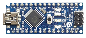
A built-in USB connector makes it easy download programs. Has both 3.3V and 5V outputs for sensors and the radio.
Arduino Pro Mini
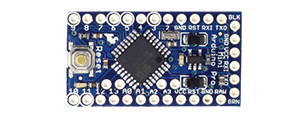
Small and low-cost! Exists in two variants. 3.3V which uses 8MHz clock and 5V which runs at 16Mhz. Regulator for sensors and radio might be necessary.
The Arduino board hosts a microcontroller [from ATmega] that is a small, low-cost, low-power computer that can run a single application. You can also find power regulators and other passive components to help get things going. The Arduino spec is not very impressive but it is ideally suited for our needs.
The Arduino doesn't have an Operating System the way that your computer does; it just runs a single application or "sketch", commonly called firmware or an embedded application, that can be as simple as a few lines of code, or very complex, depending on what you want to do.
Microcontrollers are particularly good at controlling things; hence the name. They all have a set of “pins” [the small rails with holes or legs sticking out on the sides off the chip] that are called GPIO [General Purpose Input and Output] pins, or I/O pins that can be connected to sensors or buttons to listen to the world, or to lights and relays to control your world.
Here are some technical details [you can skip this part if you aren't interested in the technospeak].
| Digital I/O Pins | 14 | Used to sense or control the environment in a binary manner. |
|---|---|---|
| Analog Input Pins | 8 | Analog inputs that measure a voltage level of 0-5 VDC with a precision of 1024 increments. Analog pins are often used for things like sensing the light level or measuring current consumption in amperes. |
| Flash Memory | 32 KB | This is where the single-application program or "sketch" program is stored when you download it from a computer. |
| SRAM | 2 KB | While the program runs, it keeps temporary data and variables in this memory. This is volatile memory so the data and variables are deleted when you turn you sensor off. |
| EEPROM | 2 KB | The program can store some more permanent data here. This is non-volatile memory so the data and variables will still be here after sensor has been restated. |
| Clock speed | 8/16Mhz | Battery-operated sensors should use a low clock speed to reduce power consumption. The Arduino Pro Mini is available with both 8 and 16 Mhz models. |
You can read more about Arduino and how to download examples here.
The radio
In order to communicate between and collect data from your sensors, we need a wireless communications link. Currently we support a couple of small transceiver called nRF24L01+ and RFM69. You can also run the MySensors library directly on the WiFi enabled ESP8266 for sensors not running on batteries.
It's pretty smart, small, low-cost and does not consume a lot of battery power.
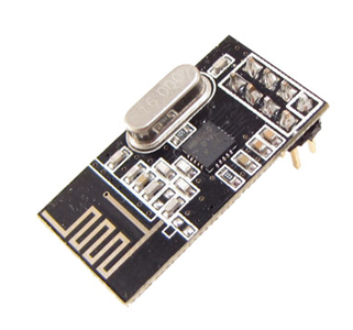
Front - You can see the nRF-chip, clock-crystal and a small antenna.
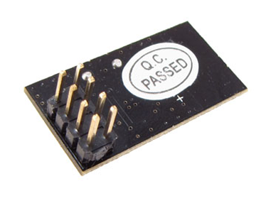
Backside - Pins for connecting it to your Arduino.
This guide describes in detail how you connect the radio to your Arduino.
Connecting the parts The absolute easiest way to connect the radio and sensors to your Arduino is by using breadboard jumper cables (a.k.a dupont cables).
They are solder-free and come in three different models; Male to Male, Female to Male and Female to Female [surprise!]. You can buy them in sets of 40 and they look something like this:
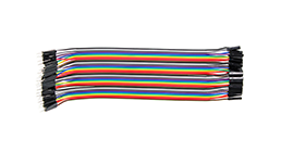
40 per set
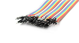
Male connector
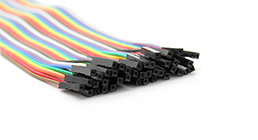
Female connector
Sensors and actuators
When a radio is hooked up to your Arduino, all you have to do is to find a suitable task for for it. There are literally hundreds of different sensors that you can use.
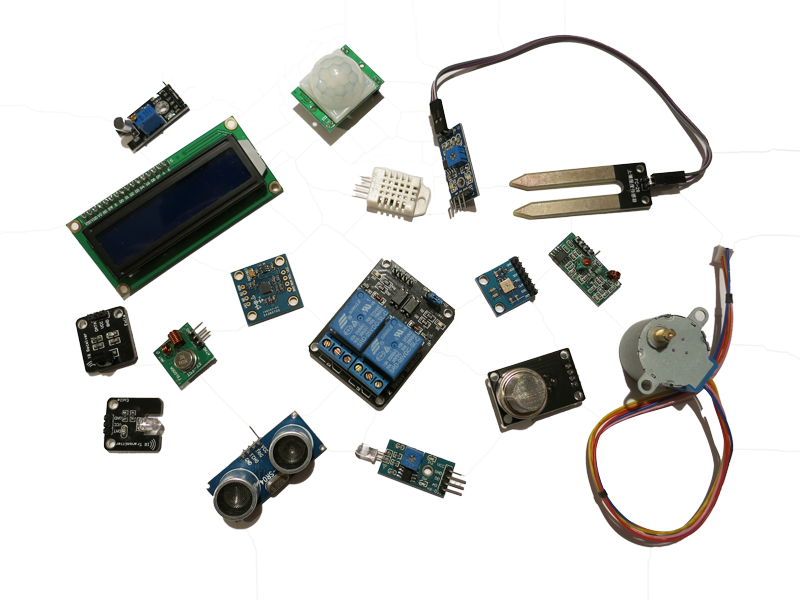
Several of the common sensors that you can use for your project are shown in the photo above; a humidity and temperature sensor, a light sensor, an ir sensor, relays, a stepper-motor, a gas sensor, a sound sensor and much more.
We provide easy-to-follow build instructions in the left column accompanied by examples that will "just work" out of the box!
Finally, to help you select all the right hardware parts that you will need, checkout our buying guide.
Software
In addition to the hardware parts, you will glue things together with some re-usable software modules or parts. In the geek-world these software modules are called libraries. Libraries provide a specific purpose such as communicating with the sensors you attach to the Arduino board.
For our examples, you won't need to worry about selecting libraries because we've already bundled them with the examples. At least not until you start combining different sensor examples into one super-duper-multi-sensor [that will spontaneously grow intelligence and take over the world].