Hi,
A friend asked me if I would be able to make a RollerShutter node. Yeah, new challenge for me! I am happy to share with you my work :smile:
This is a board for controlling rollershutters (0-100%) and detecting end stops with ACS712 for current sense of motor. It can control 3-wire motor only (Power, Up, Down wires), DC or AC, 12 to 230V. It's fine for me as I'm using AC motor. But this board can't work with 2wire DC motor. You can connect 3 push buttons (UP/DOWN/STOP) and/or external i2c device (for tactile, gesture...).
**Important Note : I share this work for educational purpose. Be very careful with this. It's an AC Board which can be lethal. If you don't know what you are doing, I can't tell you enough to not do anything. **
*Note : the link above for buying pcbs is only for RFM69 version for the moment. **General specs :
|Specs| | |---|---|---| |Size |44.4*45.4 (mm) | | Components size | 0805 | | MCU | Atmel328p TQFP | | Radio | two versions : NRF24 smd or RFM69CW | | Authentication security | ATSHA204A chip footprint | | OverTheAir update | SPI flash eeprom footprint | | Current Sensor | ACS712 5Amp current flow sensors footprint with opamp signal condition. to have a nice 0-3V ADC curve | | Relays | 2x 10Amp relays : OMRON G5Q type, 1xNO, 1xNO-NC for their footprint and quality| | AC/DC Stepdown | HILINK_HLK-PM01 230V->5V | | Screw terminals | 5mm pitch. Input AC, Motor Power Source, Motor Direction| | Extension connectors | 3x JST 1mm pitch connectors : FTDI, AVRSPI, IOs |
Onboard safety
- Varistor
- 5Amp fuse on AC Mains Input to handle relays.
- 1Amp fuse for Hilink AC/DC Stepdown.
- DS18B20A sensor for monitoring AC/DC step down temperature.
- A dual relay driver to handle relays and parasite.
- Milling slots for additional creepage.
- you can also : put some liquid tape on your AC pcb pads, and use an insulating box.
Extension Connectors description
- FTDI : JST 1mm pitch connector
- AVRSPI : JST 1mm pitch connector
- IOs : JST 1mm pitch connector -> 3V/GND/A4/A5/D3, for UP/DOWN/STOP buttons or I2C for external breakout (tactile switch, gesture...) or some shields I have designed :)
AC Connectors description
| Connector | |
|---|---|
| Input AC | connect to AC line L to Live and N to Neutral |
| MotorPowerSource | for 12-24VDC just connect power source to 12_230 screwterminal, for 110-230V connect together the pins from Motor Power screwterminal |
| Motor Direction | Motor Up and Down lines |
Arduino Pin description
| Arduino sketch define | Arduino Pin | description |
|---|---|---|
| MY_OTA_FLASH_SS | 8 | EEprom CS pin |
| ATSHA204_PIN | 17/A3 | Arduino Digital I/O pin number for ATSHA204A sot23 ic (for authentication) |
| RELAY_UPDOWN | 15/A1 | Digital I/O pin number for relay SPDT |
| RELAY_POWER | 16/A2 | Digital I/O pin number for relay SPST : Normally open, power off rollershutter motor, if A2==1 and A1==0 moveup, if A2==1 and A1==1 movedown, if A2==0 power off |
| DEBUG_LED | 6 | Digital I/O pin number for onboard debug led |
| BUTTON_STOP | 3 | Digital I/O pin number for button Stop |
| BUTTON_UP | 18/A4 | Digital I/O pin number for button Up or I2C |
| BUTTON_DOWN | 19/A5 | Digital I/O pin number for button Down or I2C |
| ACS712_SENSOR | A7 | ADC pin for ACS712 current sensor |
| DS18B20_PIN | 4 | One Wire Temperature sensor for onboard monitoring |
Q&A about my personal choice
Why not an ESP?
- I like these chips. But I don't want wifi for my rollershutter nodes. I prefer to use subghz radio+atsha signing ic.
Why current sensor for endstop detection?
- There are other option for just detecting a simple trigger, sure. I looked at it briefly, there was not a so big footprint saving, and I thought the current sensor would add more verstality to the board.
Why so much capa, using filtering for analog etc..
- some ferrites, caps etc. are not all mandatory. they help to improve things but without some parts it works well. It's there, in case, for debug, and still useful when there are some footprints available.
etc..
Finally :
- as each new thing I make, I enjoy the new challenge.
- I have tried to make a board dedicated for RollershutterNode with autocalibration, with as much features/options/versatility I could with the available footprint.
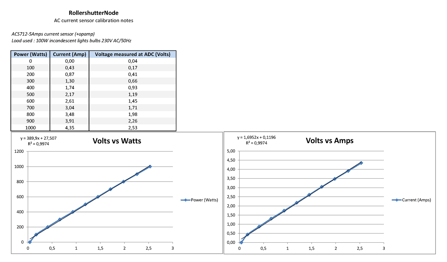
About the ACS current sensor
ACS reading measurement results, from 0 to 1000W by 100W step :
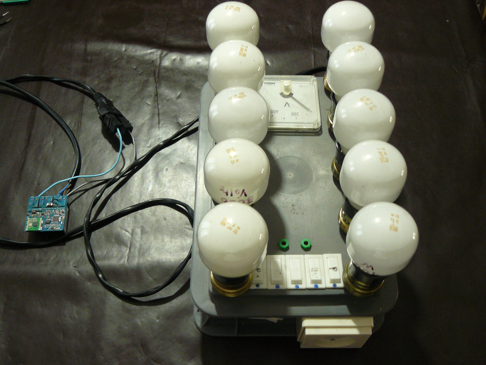
 For fun, this is the light bulbs I have used to do my measurements (5 lights bulbs can be powered separately, the other row in one time, so it's possible to do 100W steps)
For detail about opamp circuit see schematic.
Example of use of this board : RollershutterNode
How is the Rollershutter motor controlled:
On-board, there are 2x10Amp Relays. Rollershutter motor don't use 10Amp of course, nor 5Amp. May we expect no need of snubber, if using over rated relays? I hope :) If mandatory for you then, it should be external, not enough space onboard. That said, for a simple relay board too, you can control lot of thing with 10amp.
So, we have 2 relays, for the rollershutter:
- 1x NO which enable/disable power on the second relay. It is like "Stop Motor".
- 1X NO-NC that you can toggle, and drive Up, or Down the rollershutter motor. Remember this relay needs to be enabled by the previous one. So relays are "interlocked", you can't enable "Up" and "Down" outputs to motor at same time and burn your motor.
How to open/close 0-100%
We need to detect the up and down endstops. It is managed by the onboard ACS7125 sensor. It will senses the motor current flow and we will read it with ADC on arduino. When motor is active, there is a power consumption. And when an up or down end is toggled, the motor stops (because of mechanical switch...). There is no power consumption.
As you can see, with ACS712, we can know in which state we are. We are able to read some kind of power consuption curve too if needed and no mechanical ends switch available.. So, we need to know how long it takes to open the rollershutter, and to close (it may be not the exact timing open vs close time).
Example sketch
Note: the example sketch is for Mysensors v2.x. You can find it in example folder. It is state machine based, so no blocking loop. It's not very polished but it's working. I miss time, too much ideas&projects..I will look at it later.
- You just need to config your settings in the MyNodeDefinition.h
- The ShutterSM.h and .cpp are the state machine for the shutter. You don't need to modify it, there are default settings.
- State and settings of rollershutter are stored in eeprom.
The sketch present the following Mysensors CHILD_IDs, presented to a controller for instance :
| CHILD_ID | Description | |
|---|---|---|
| CHILD_ID_ROLLERSHUTTER | handle UP/DOWN/STOP/PERCENT | |
| CHILD_ID_AUTOCALIBRATION | remotely start a calibration | |
| CHILD_ID_TEMPERATURE | onboard temperature sensor, to monitor board&Hilink temperature | |
| CHILD_ID_ENDSTOP | endstop. for debugging in case...Set it to simulate an endstop during calibration and tell the node that the shutter has reached the endstop (in case no mechanical switch etc..) | |
| CHILD_ID_PERCENT | Rollershutter PERCENT for controller which are not Mysensors 2.0 compliant yet | |
| CHILD_ID_CURRENT | Current sensor value, for debugging.. |
At first launch, the node will use the default values in the state machine and will know it's not calibrated. So, you can launch a calibration. That will automatically :
- fully open the shutter.
- fully close it and measure travel time.
- fully open it and measure the travel time.
- Done. Yeah! Parameters are stored in eeprom.
- If you push Up button, that will try to fully open. Down, Stop buttons will do their job too. The node store the new position in eeprom. From your controller, set a PERCENT and that will open as you want your shutter. so fun, so cool :) etc..
**Notes **
TODO
- 3d insulating case
- improve things. always improve :)
Donations
I'm trying to make opensource projects. I do this for free and sharing spirit. I don't do ads etc.. But if you think information here is worth of some money, or want to reward me, feel free to send any amount through paypal.

Or you can also order pcb through openhardware.io and pcbway. I will earn a little percentage that will allow me to order proto pcb and share more fun design.
Or pay me a protein smoothie if you see me! oh well, a beer is great too :)
Contributors
Special thanks to:
- Mysensors Team for its so great lib
- Adafruit, Sparkfun, TI, Atmel etc.. for all educational infos they share
Links, reference and license
https://github.com/scalz/MySensors-HW/tree/development/RollerShutterNode
Copyright Scalz (2016). released under the CERN Open Hardware Licence v1.2
This is an opensource hardware. So please respect at least license and do what you want with it ;)
Enjoy :)