
MySensors Wireless IoYT Dollhouse!
The MySensors core team hosted a booth at the Eindhoven Maker Faire 2017. To demonstrate the capabilities of the MySensors framework, I (Yveaux) scaled down a real house to dollhouse size, and stuffed it with sensors and actuators. This video by Tbowmo shows some of the tricks it has up its sleeve:
I've had many requests to write up on the dollhouse, so here it is!
This page shows you how the nodes were created, so you can build them yourself!
I specifically designed a sensor node for the dollhouse. It is spread throughout the house, small enough not to disturb the looks of the dollhouse. This sensor node is basically an Arduino Pro Mini with an SMD nRF24L01+ radio and a CR2032 battery holder. You can build your own, or build a setup using a regular Arduino.
Some remarks upfront:
- Due to the large amount of sketches and sensors I will not be able to update the sketches or hardware designs when libraries change or hardware becomes obsolete.
- The dollhouse sketches are shared on my github page
- Make sure all required libraries are installed, which are described in the readme. The exact SHA of each library version I used for compilation is included, so if you run into troubles try these exact version first!
- I use a small 'library' called DemoSensorConfig which is shared by all sketches. It contains the MySensors network configuration, node ID's and some LED blinking code in a single location. To run a sketch standalone only the relevant parts from DemoSensorConfig have to be copied to the sketch (replace the DemoSensorConfig #include).
Sensors
This overview shows all sensor and actuator nodes spread throughout the house, and how they are powered.
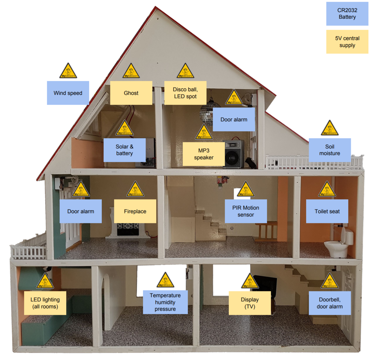
Build instructions for each sensor will be presented further down this page.
Controller
A Raspberry Pi 3 is used as a controller. It is running a default Raspbian Jessie install and Node-Red controls the logic.
The MySensors nodes node-red-contrib-mysensors are used to de- and encode the MySensors serial protocol from the serial gateway. From there the data flows to MQTT (pubsub middleware) which is used by Node-Red to communicate withe the sensors and actuators in the house. MQTT could have been left out, but I find it convenient to separate the wireless network from the control logic and at the same time be able to control or monitor the network from the outside.
Google AIY
Scenes and actions in the house can either be triggered by Node-Red, sensors or voice control. The voice recognition is performed by Google AIY, which basically allows you to run Google Assistant on a Raspberry Pi. As I don't own a Google Voice Kit, a regular microphone was used to capture the voice commands -- thanks Hackaday. The voice recognition works quite well, even in a noisy environment like the Maker Faire.
Inspired by this site, I changed the AIY code to publish all recognized texts and the Assistant state to an MQTT topic:
src/action.py:
# This modification will send all recognized commands to MQTT topic 'aiy/speech'.

class Mqtt:
    def __init__(self, say, keyword):
        self.say = say
        self.keyword = keyword

    def run(self, voice_command):
        # Get string
        print ("Command:"+voice_command)
        words = voice_command.lower().split()

        cmd = "mosquitto_pub -t \"aiy/speech\" -m \"" + voice_command + "\" >/dev/null"
        print (cmd)
        subprocess.check_output(cmd, shell=True).strip()

def make_actor(say):
    ....
    actor.add_keyword(_('(.*)'), Mqtt(say,_('dontcare')))
    ....
src/actionbase.py
# ADD TO TOP
import re

# CHANGE:
class KeywordHandler(object):
    ....
    def can_handle(self, command):
            return self.keyword in command.lower()
    ....
    def handle(self, command):
        if self.can_handle(command):
            self.action.run(command)
            return True
        return False

# INTO:
class KeywordHandler(object):
    ....
    def can_handle(self, command):
        if ("*" in self.keyword):
            match = re.match(self.keyword.lower(), command.lower())
            if match:
                return True
        else:
            return self.keyword in command.lower()
    ....
    def handle(self, command):
         if ("*" in self.keyword):
             match = re.match(self.keyword.lower(), command.lower())
             if match:
                 param = match.group(1)
                 self.action.run(param)
                 return True
         else:
             if self.can_handle(command):
                 self.action.run(command)
                 return True
             return False
src/main.py
# Publish assistant status to MQTT topic 'aiy/status'

# ADD TO TOP
import subprocess

# ADD
class StatusUi(object):
        ....
        cmd = "mosquitto_pub -t \"aiy/status\" -m \"" + status + "\" >/dev/null"
        subprocess.call(cmd, shell=True)
Install AIY as a service to run at startup, as described here.
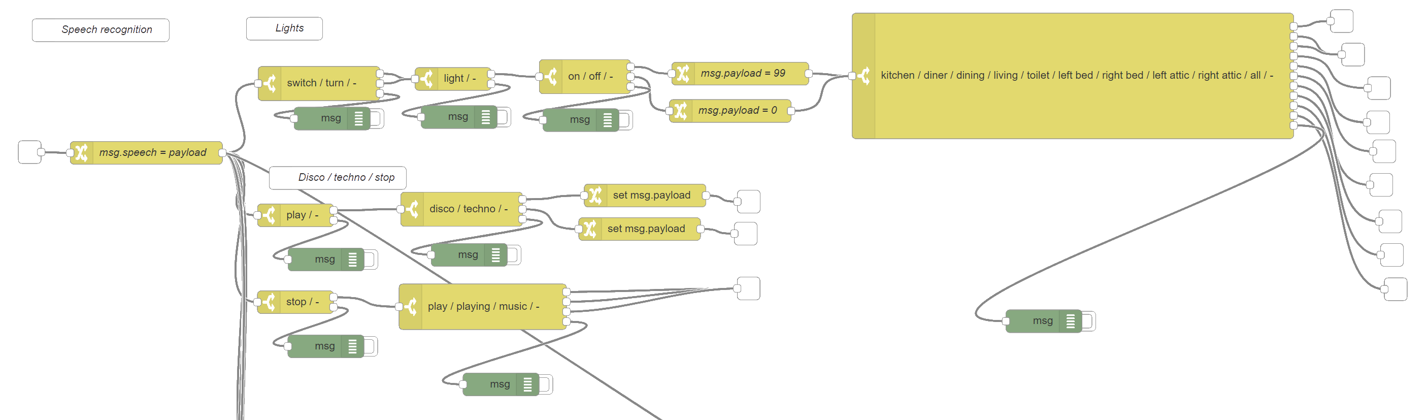
Node-Red subscribes to the aiy/speech MQTT topic and tries to dissect the speech commands into sequences of known commands. If a sequence is recognized (e.g. 'switch', 'light', 'kitchen' and 'on') it will trigger an action. Part of the flow is shown in the following picture:
Powering
A PC ATA power supply's 5V output is used to power the house. The LED lighting alone requires roughly 40 Watts in its brightest setting, rest of the nodes add a few Watts at most.
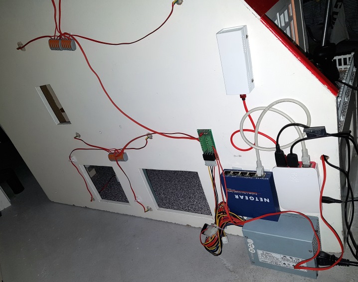
At the bottom right you see the Raspberry Pi 3, a network switch and the PC power supply. The white box on top is the serial gateway. A small custom PCB distributes 5V from the PC supply to a few power strands, which connect to Wago terminal blocks. From there connections are made to dollhouse-sized wall sockets. The 5V supplied nodes are connected through a mating plug, the battery nodes all run on CR2032 coin cells.
Gateway
USB Serial MySensors Gateway that allows the wireless sensor- and actuator nodes to communicate with the controller.
Hardware
- Arduino nano
- nRF24L01+ radio
- Perfboard
Connect
- Just follow the instructions on the serial gateway build page
Sketch: GatewaySerial
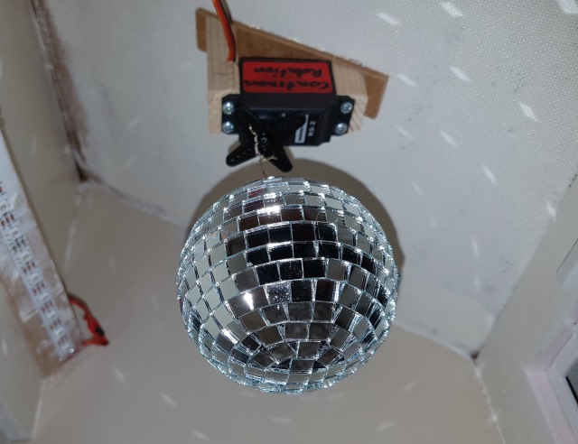
Discoball node
A 5V powered node, using a modified servo to rotate a discoball at various speeds and switch a LED spot.
Hardware
- Dollhouse Wireless Node, 5V powered through RAW pin (node runs at 3.3V)
- Servo, modified for continuous rotation. I used a Modelcraft RS-2 type, but these are all more or less identical.
- 3D printed LED spot
- White LEDs + resistors mounted inside the spot (I had some left from hacked Ikea Molgans).
- Mosfet to switch the LEDs
- Mini disco ball
Connect
- Servo to 5V, GND and signal to Arduino IO 6 (pin 8 on the addon connector)
- LED control to Arduino IN A4
- Use some wire to connect the discoball to the servo wheel. Mount the servo upside-down.
Sketch: Discoball
For testing purposes the ball can also be rotated by commands from the serial console.
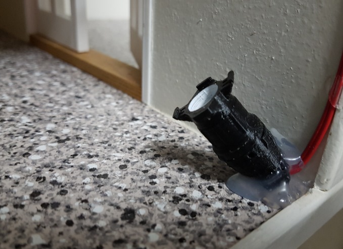
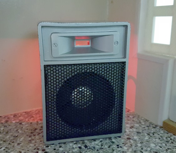
Sound & music node
A 5V powered node, using a JQ6500 MP3 player module, all built into a small speaker.
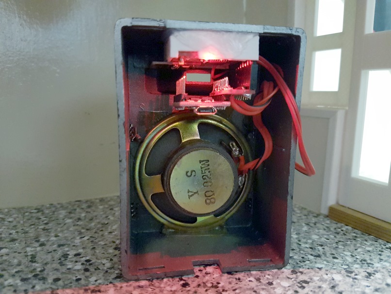
Hardware
- Dollhouse Wireless Node, 5V powered through RAW pin (node runs at 3.3V)
- 8 Ohms speaker
- JQ6500 MP3 player module
Connect
- Power the JQ6500 from 5V
- The JQ6500 TX pin should be connected to Arduino IO 7 (pin 9 on the addon connector)
- The JQ6500 RX pin should be connected to Arduino IO 8 (pin 10 on the addon connector)
I used a piece of perfboard to stack the JQ6500 to the dollhouse node, so it would fit inside the speaker.
Sketch: Mp3Player
The samples (included with the sketch) need to be downloaded to the module's internal flash before it can be used. Refer to elecfreaks for a description.
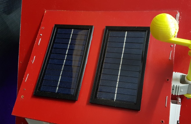
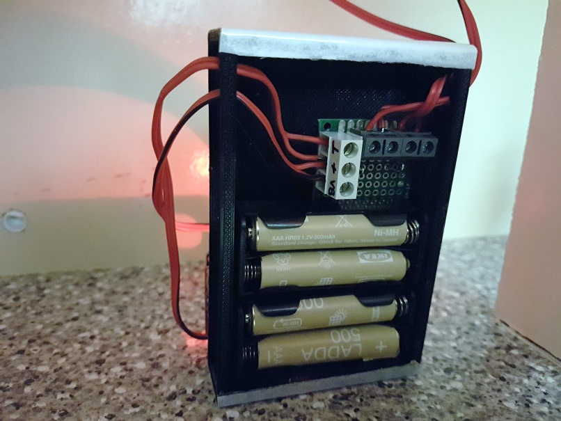
Solar & powerwall node
A standalone node, powered from 2 solar panels or 4 x AAA rechargeable batteries. Depending on the amount of sunlight available, the node will automatically switch between solar or battery power. A bi-directional power sensor monitors whether the node is powered from the solar panels or the batteries.
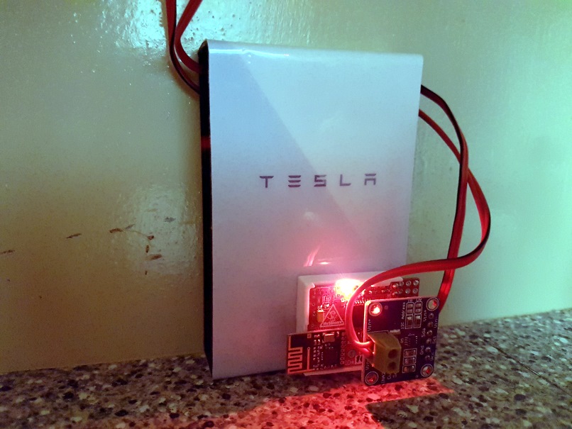
Hardware
- Dollhouse Wireless Node, powered through RAW pin (node runs at 3.3V)
- INA219 power sensing module
- 4 x AAA rechargeable battery and holder
- 2 x 6V, 1W solar panel
- 2 x 1N4148 diode
- 2 x 3D printed solar panel frames
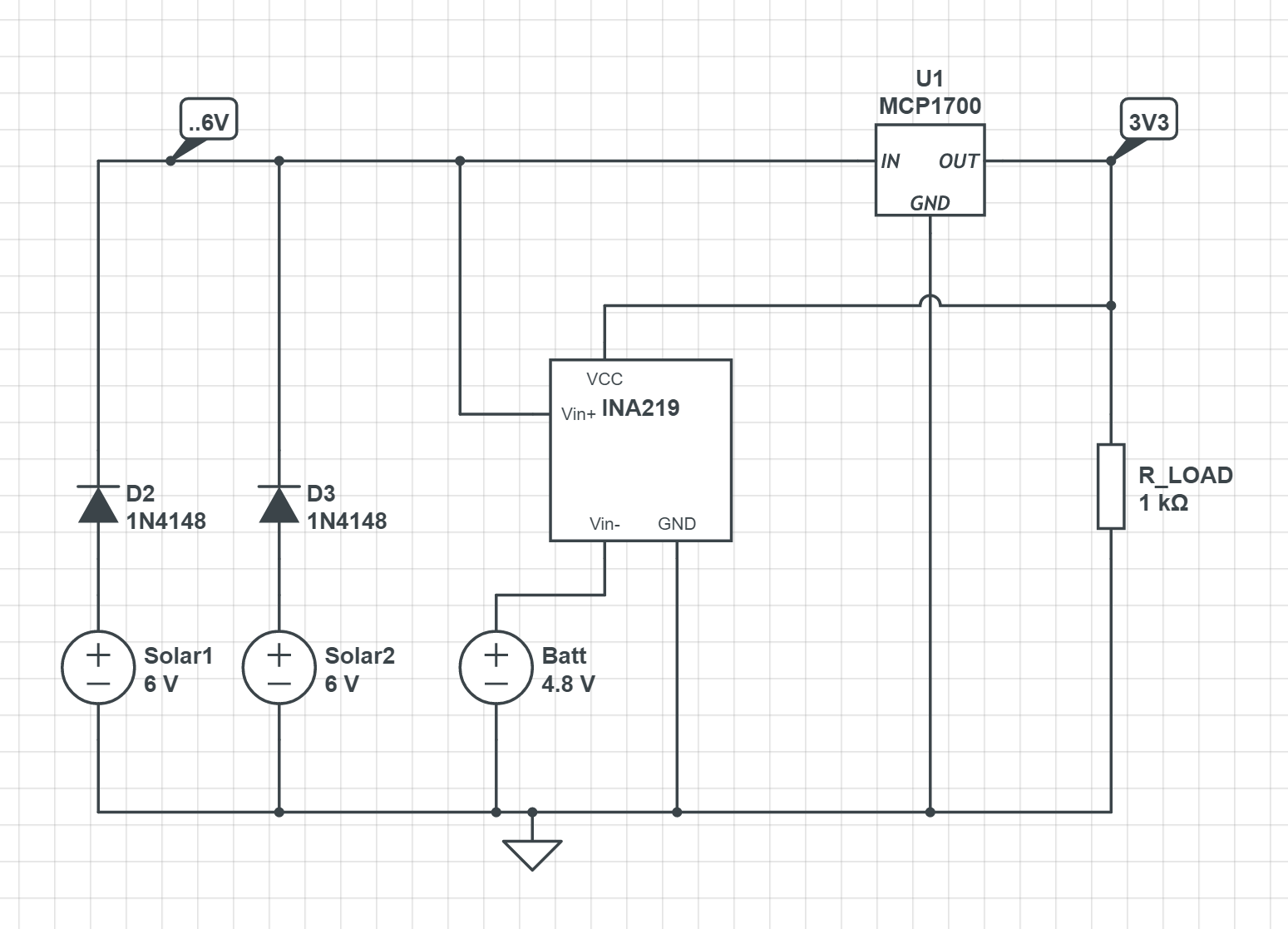
Connect
- Use the schematic above as a reference.
- MCP1700 is the dollhouse node's voltage regulator; R_Load is the dollhouse node.
- INA219 SCL to Arduino IO A5 (pin 5 on the addon connector)
- INA219 SDA to Arduino IO A4 (pin 6 on the addon connector)
Sketch: Solar
Fireplace node
A 5V powered node, using 2 x WS2812B RGB LEDs to simulate a burning fire.
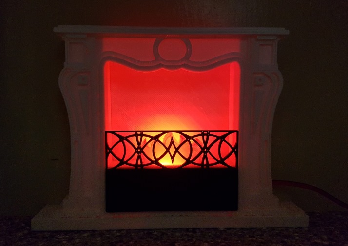
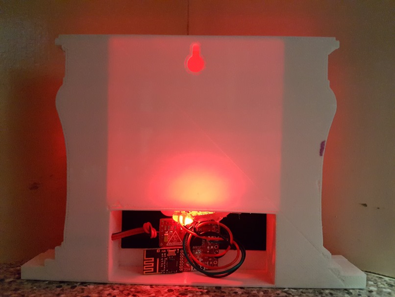
Hardware
- Dollhouse Wireless Node, 5V powered through RAW pin (node runs at 3.3V)
- 2 x WS2812b breakout boards
- 3D printed fireplace
Connect
- The first LEDs DI pin to Arduino IO 6 (pin 8 on the addon connector)
- Chain the DO of the first to the DI of the second LED
- Power the LEDs from 5V
Sketch: Fireplace
Toilet node
A sleeping sensor node that detects opening and closing of the toilet seat lid.
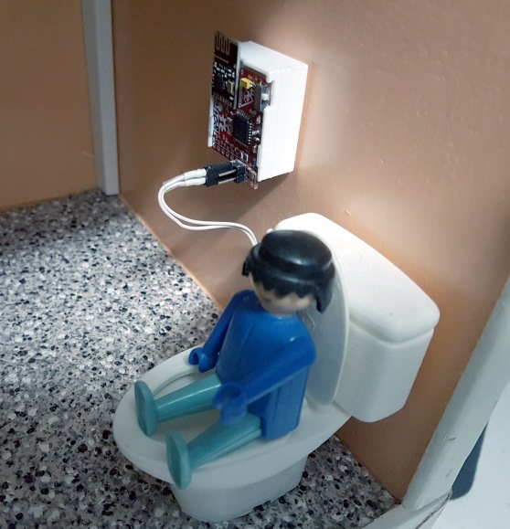
Hardware
- Dollhouse Wireless Node, CR2032 powered
- 3D printer toilet
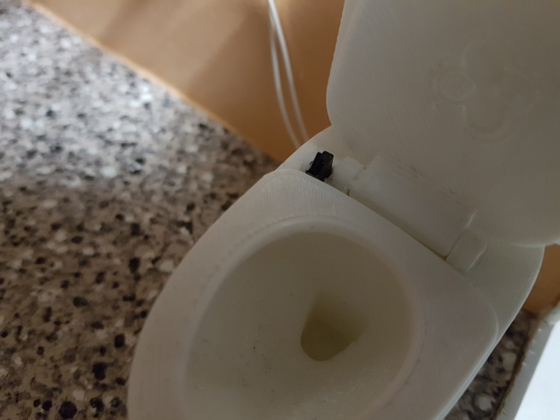
- A small (micro) switch to detect state of the lid.
Connect
- The switch to GND and Arduino IO 2 (INT0, pin 3 on the addon connector)
- Solder 1MOhm resistor to R4, or activate internal pull-up in the sketch (higher sleeping current)
Sketch: Toilet
Wind sensor node
A sleeping sensor node that detects pulses from a reed switch triggered by a revolving magnet.
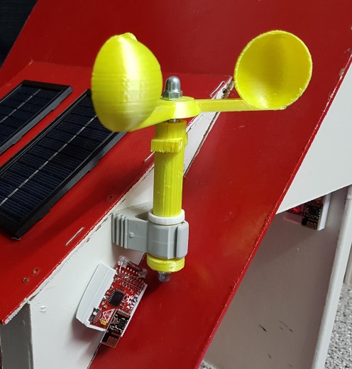
Hardware
- Dollhouse Wireless Node, CR2032 powered
- Small reed switch
- Magnet (neodymium preferably)
- 3D printed anemometer
Connect
- The reed switch to GND and Arduino IO 2 (INT0, pin 3 on the addon connector)
- Solder 1MOhm resistor to R4, or activate internal pull-up in the sketch (higher sleeping current)
Stick the magnet to the bottom revolving disc of the anemometer and position it close to the reed switch.
Sketch: WindSpeed
The sensor can be calibrated to return the speed of revolution in Km/h by modifying the KmHPerRevsSec parameter in the sketch.
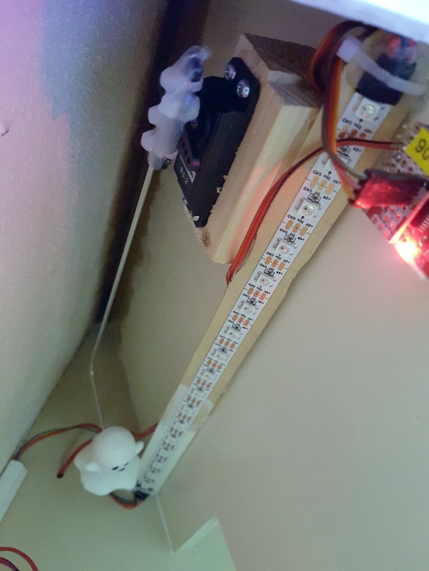
Ghost node
A 5V powered node, which uses a servo to have a hidden ghost appear from under the rooftop. Triggered by MySensors the ghost moves to the front of the dollhouse, wiggles for a few seconds and then moves back to its hideout again.
Hardware
- Dollhouse Wireless Node, 5V powered through RAW pin (node runs at 3.3V)
- Servo. I used a Modelcraft RS-2 type, but these are all more or less identical.
- 3D printed ghost - I lost the link...
- Bicycle spoke
Connect
- Servo to 5V, GND and signal to Arduino IO 5 (pin 7 on the addon connector)
- Bend the spoke a few cm's from the end. Drill a small hole in the ghost and mount the short end of the spoke to the ghost (hot glue!).
- Mount the other end to the servo arm (tie-wraps, hot glue) and fix the servo just below the roof.
Sketch: Ghost
For testing purposes the ghost can also be moved by commands from the serial console.
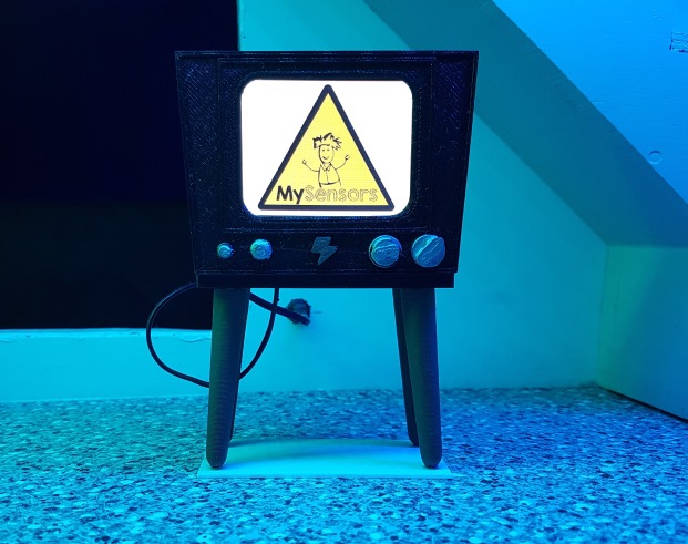
TV node
A 5V powered node, which decodes & displays jpeg images on a small TFT screen, plays a game of pong or displays custom text. This node requires more processing power than a regular ATMega to decode the jpeg images and needs storage. Therefore it is based on an Esp8266 instead of the Dollhouse node. However, the WiFi of the Esp8266 is not used.
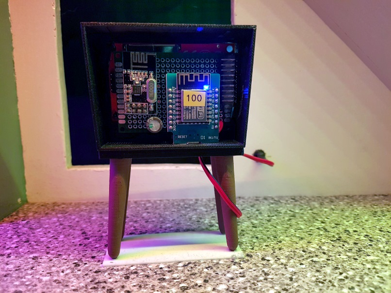
Hardware
- Wemos D1 Esp8266 development board
- nRF24L01+ radio
- ILI9341 display 2.8" 320x240. I don't know where I got it from, but the one in the link looks identical to the display I used.
- Perfboard
- 3D printed retro television
Connect
- Refer to the MySensorsTV sketch to connect the display and radio to the Wemos D1.
Sketch: MySensorsTV
Modify the TFT_eSPI library User_Setup.h file in the following way:
#define TFT_CS   D8  // Chip select control pin D8
#define TFT_DC   D3  // Data Command control pin
#define TFT_RST  -1  // Set TFT_RST to -1 if the display RESET is connected to NodeMCU RST or 3.3V
The sketch presents two child-ID's: one for commands and one for direct text display. The following commands are recognized:
- c64 - Display a Commodore-64 startup screen with blinking cursor, implemented as alternating display of 2 jpeg images
- pong - Plays a game of pong, by itself
- or a jpeg filename on the Esp8622's spiffs storage
Use the esp8266fs plugin to upload the jpeg images in the 'data' folder to the Esp's flash file system.
PIR alarm node
A sleeping sensor node, capable of detecting motion using a PIR sensor.
Hardware
- Dollhouse Wireless Node, CR2032 powered
- AM312 Mini PIR module
Connect
- Power the PIR from the 3V3 and GND on the addon connector. Some modules have a small + and - silkscreen print, but mine didn't. Make sure the polariry is ok!
- The PIR trigger signal to Arduino IO 2 (INT0, pin 3 on the addon connector)
Sketch: PirMotion
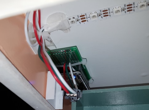
Lighting node
A 5V powered node, which controls a WS2812B LED strip of 127 LEDs. The single LED strip runs through the whole house (only extended by some wires to bridge the different floors). It uses a modified version of the WS2812FX library to display all kinds of LED blink patterns, either in single rooms or for the whole house. The WS2812FX requires quite a large amount of flash so I started stripping down a version to run on an ATMega328. I couldn't get the node to perform reliably before the Maker Faire and decided to quicly switch to an ESP8266 NodeMCU, connected as a serial gateway with local 'sensors' (the LED strip) to the Raspberry Pi. This is the only wired node in the dollhouse, but still running in the MySensors network as an extra gateway!
Hardware
Connect
- The LED strip must be powered directly from a beefy 5V supply. With all LEDs turned on it draws around 40 Watts!
- Both the beginning and end of the strip must be connected to the power supply. Otherwise the voltage drop over the LED strip will change the LED colors near the end of the strip.
- LED strip DI pin to NodeMCU pin D4.
Sketch: Lighting
The sketch will present a 'sensor' for each room in the house, and a separate 'sensor' to address the whole house.
Following messages types are supported:
- V_RGB - set RGB color. Format RRGGBB, in hex.
- V_DIMMER - change brightness. Format value [0..100]
- V_STATUS - switch light on/off. Format 1/0.
- V_VAR1 - run a blink pattern. Format 'mode,color,brightness,speed', where mode is a WS2812FX mode value [0..46] (refer to FX_MODE_xxx ), color is RRGGBB (in hex), brightness is a value [0..100] and speed is a value [0..100].
The sketch includes some 'intelligence' in case e.g. a pattern for the whole house is active and an individual room is switch. This will stop the whole house pattern and switch to individual room pattern.
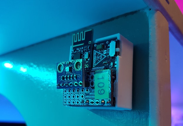
Temperature, relative humidity & pressure node
A sleeping sensor node, capable of monitoring environmental temperature, relative humidity and pressure.
Hardware
- Dollhouse Wireless Node, CR2032 powered
- BME280 sensor module
Connect
- BME280 Vcc and GND to addon connector VCC and GND.
- BME280 SCL to Arduino IO A5 (pin 5 on the addon connector)
- BME280 SDA to Arduino IO A4 (pin 6 on the addon connector)
- BME280 CSB and SDO remain unconnected
Sketch: TemperatureHumidityPressure
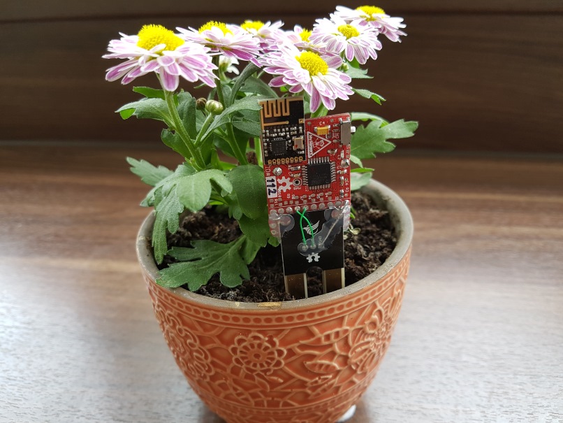
Soil moisture node
A sleeping sensor node, capable of monitoring soil moisture.
Hardware
- Dollhouse Wireless Node, CR2032 powered
- Soil moisture sensor
Connect
- I removed the bulky cable connector to be able to connect the sensor PCB directly to the sensor node, using a breadboard addon PCB.
- Sensor GND to addon connector GND.
- Sensor Vcc to Arduino IO pin 5 (pin 7 on the addon connector)
- Sensor output to Arduino IO A4 (pin 6 on the addon connector)
Sketch: SoilMoisture
The sketch reports the soil moisture value in [cb] (staturated soil = 0 [cb], dry soil = 200 [cb]), but uses a simple linear mapping based on ADC value in water and in air. For serious use this sensor will need some calibration!
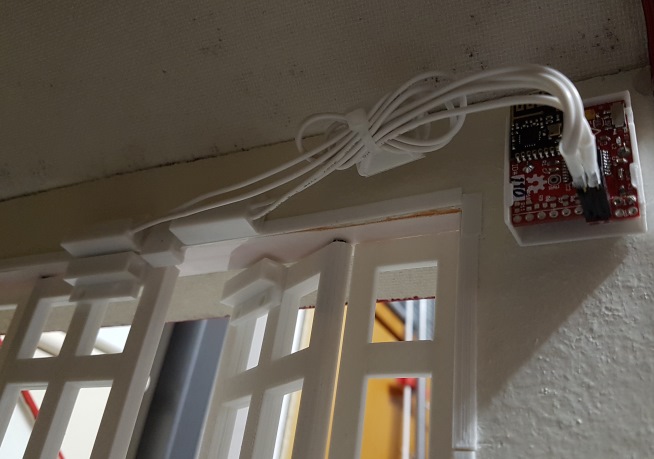
Door alarm node
A sleeping sensor node, capable of monitoring 2 door sensor switches.
Hardware
- Dollhouse Wireless Node, CR2032 powered
- Magnetic Door Switch Sensors
Connect
- One door switch sensor to GND and Arduino IO 2 (INT0, pin 3 on the addon connector)
- One door switch sensor to GND and Arduino IO 3 (INT1, pin 4 on the addon connector)
- Solder 1MOhm resistors to R4 & R5, or activate internal pull-ups in the sketch (higher sleeping current)
Sketch: DoorAlarm
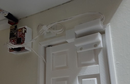
Frontdoor node
A sleeping sensor node, capable of monitoring 1 door sensor switch and a momentary doorbell switch.
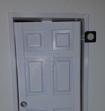
Hardware
- Dollhouse Wireless Node, CR2032 powered
- Magnetic Door Switch Sensor
- Momentary doorbell switch (normally-open)
Connect
- The doorbell switch sensor to GND and Arduino IO 2 (INT0, pin 3 on the addon connector)
- The door switch sensor to GND and Arduino IO 3 (INT1, pin 4 on the addon connector)
- Solder 1MOhm resistors to R4 & R5, or activate internal pull-ups in the sketch (higher sleeping current)
Sketch: FrontDoor
Breadboard node
A sleeping sensor node, built on a breadboard, with a single pushbutton. This node is not part of the dollhouse, but is used to demonstrate a simple sensor on a breadboard which can control the house.
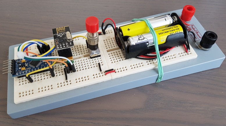
Hardware
- Arduino Pro Mini
- nRF24L01+
- 2xAA Battery holder + batteries
- Pushbutton
For long battery life desolder the power LED and voltage regulator.
Connect
- The radio to the Arduino
- Pushbutton to GND and pin 2
- 2xAA battery power to GND and VCC on the Arduino
Sketch: BreadboardButton