The following tips will reduce the power consumption of your Arduino Sensor allowing it to run on batteries for a longer period of time.
Note: When programming using FTDI adapter on modified 3v3 Pro Minis with removed regulators. Make sure to supply a stable 3v3 power source to the VCC pin yourself.
- Use the 3.3V version Arduino Pro Mini with the lower CPU clock speed (8MHz)
- Sleep whenever possible by powering down the Arduino and radio. The sensor node can periodically wake up by either triggering a timer interrupt or by an attached sensor registering a reading on one of the Arduino interrupt enabled io-pins. Most of the MySensors example sketches implement sleep mode. When powered down, the CPU, DS18B20 temp sensor and radio consume (very roughly) 120 uA - which is similar to the self discharge rate of a battery.
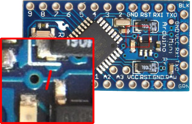
- Disconnect the Arduino's power indicator LED by cutting the track between the LED and the resistor in series or simply desolder one of them. Saves about 1.5 mA
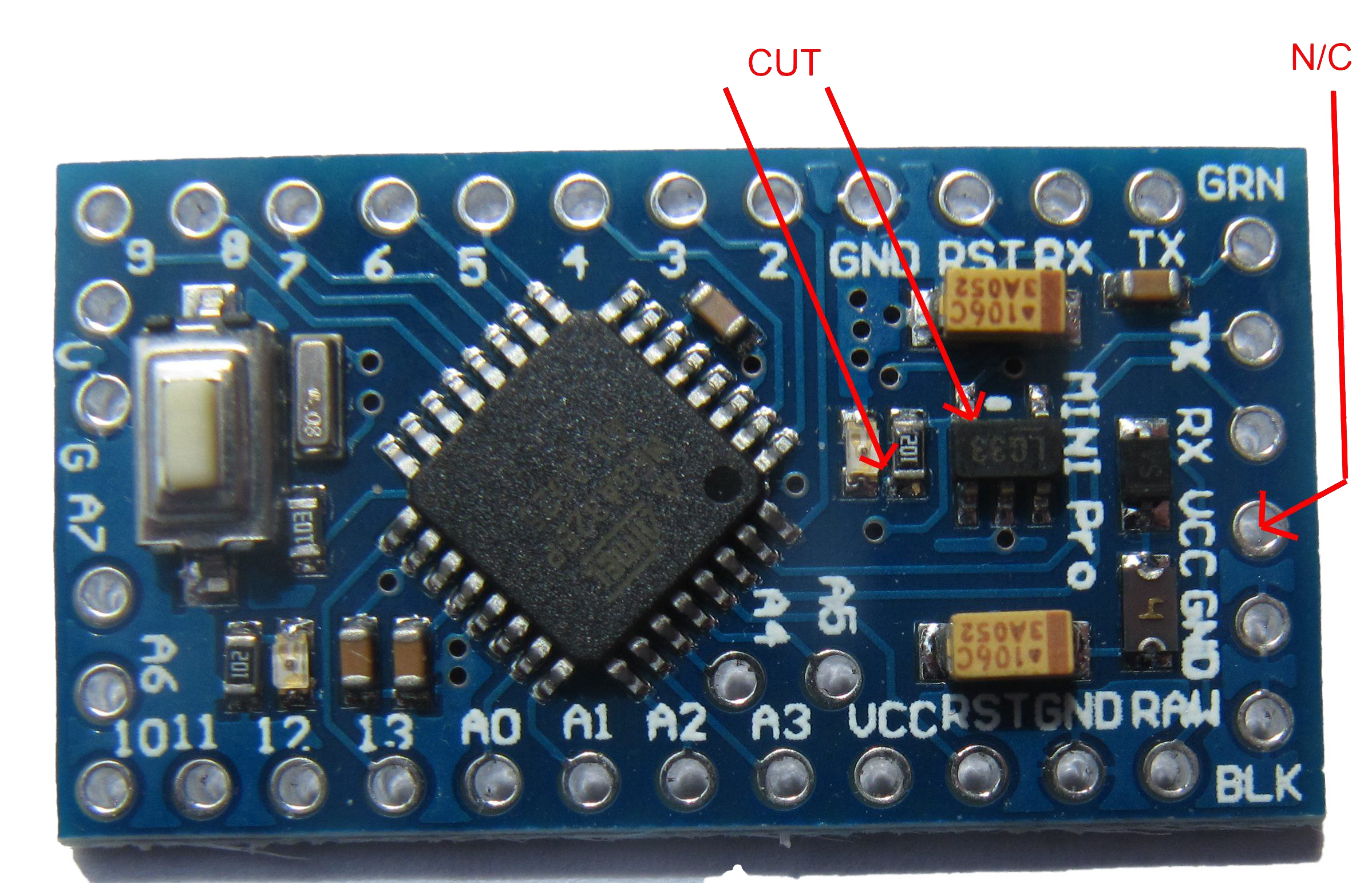
- Disconnect or desolder the 3.3 VDC regulator because it is not needed. Cut the Vout pin with a sharp fine wire cutter. See images to the right on how to locate regulator. Saves about 220 uA.
- Power the device with two AA batteries connected in series to the PCB. You can power 5 VDC sensors using an ultra low power step up converter (see the Buying Guide below). Power regulators will reduce the battery life due constant power consumption.
There were or are pro mini's, if you desolder the voltage regulator, the mentioned VCC hole is not connected anymore.
--> if you have a pro mini where this is the case, you can't use anymore the usb-to-ttl programmer like that because the pro mini won't be powered on anymore by the VCC of your programmer. You must connect the VCC pin of the programmer with a wire to the other VCC hole.
--> in the other case, like mine pro mini version, no problem, the VCC hole at the right is still connected.
Short video showing how to desolder LED and regulator:
Theoretical Battery Life
The battery life (for a hypothetical temperature sensor) can be calculated by determining the average current for the circuit, using the following general equation:
Iavg = (t0*I0 + t1*I1 ... + tx*Ix) / (t0 + t1 ... + tx)
Note these figures are for illustration purposes - your results will certainly vary. Current is measured at the battery with a battery Voltage of 3.0V.
Idling: I0 = 28 mA, t0 = 0.65 sec (using the delays I set up in the sketch) Transmitting: I1 = 31 mA, t1 = say 50 mSec (time is just a guess) Sleeping: I2 = 120 uA (very roughly), t2 = 15 minutes (the temperature sampling rate)
Using the above figures the effective current = 0.142 mA. The sleep current is difficult to measure accurately, so this figure may vary and will affect the lifetime calculation.
Assume the batteries are good for 2000 mAhr, that gives a lifetime of 14,101 hours, which equals to 19.6 months. The lifetime is dominated by the sleep current and sensor sample rate. Assuming the figures and calculations are correct (let us know if they aren't), it's likely the batteries would die from old age rather than through actual usage.
Boost your batteries
The Arduino 3.3V 8mhz can handle down to roughly 2.8V and the Nrf24l01+ down to 1.9V.
To be able to suck as much juice out of the batteries as possible you can use a DC-DC Step up booster. This booster will convert everything from 0.8V back to 3.3V. Note that a booster can be a bit noisy (and disturb the radio). The booster is also less than 100% efficient, so boosting can be less efficient than just powering the Arduino directly from the batteries and change batteries when they hit 2.8V.
It can help to connect a 0,1uF ceramic capacitor from GND to VOut. To avoid noise to the radio (NRF24l01+) you can power it directly from the batteries since it can operate down to 1.9V and only power the Arduino through the booster.
Measuring and Reporting Battery Level
There are two main strategies for measuring battery voltage. The internal measurement can only be used when the Arduino is powered directly from batteries. The external measurement needs additional components (2 resistors) and uses one of the Arduino's analog pins. The external measurement can be used for boosted nodes as well as nodes powered directly from batteries.
Internal measurement
Example code:

/*
   The MySensors Arduino library handles the wireless radio link and protocol
   between your home built sensors/actuators and HA controller of choice.
   The sensors forms a self healing radio network with optional repeaters. Each
   repeater and gateway builds a routing tables in EEPROM which keeps track of the
   network topology allowing messages to be routed to nodes.

   Created by Henrik Ekblad <[email protected]>
   Copyright (C) 2013-2026 Sensnology AB
   Full contributor list: https://github.com/mysensors/MySensors/graphs/contributors

   Documentation: http://www.mysensors.org
   Support Forum: http://forum.mysensors.org

   This program is free software; you can redistribute it and/or
   modify it under the terms of the GNU General Public License
   version 2 as published by the Free Software Foundation.

 *******************************

   DESCRIPTION

   This is an example that demonstrates how to report the battery level for a sensor
   using the internal measurement method.
   Instructions for measuring battery capacity are available here:
   http://www.mysensors.org/build/battery

*/

// Enable debug prints to serial monitor
#define MY_DEBUG

// Enable and select radio type attached
#define MY_RADIO_RF24
//#define MY_RADIO_NRF5_ESB
//#define MY_RADIO_RFM69
//#define MY_RADIO_RFM95

#include <MySensors.h>

uint32_t SLEEP_TIME = 900000;  // sleep time between reads (seconds * 1000 milliseconds)
int oldBatteryPcnt = 0;
#define FULL_BATTERY 3 // 3V for 2xAA alkaline. Adjust if you use a different battery setup.

void setup()
{
}

void presentation()
{
    // Send the sketch version information to the gateway and Controller
    sendSketchInfo("Battery Meter", "1.0");
}

void loop()
{
    // get the battery Voltage
    long batteryMillivolts = hwCPUVoltage();
    int batteryPcnt = batteryMillivolts / FULL_BATTERY / 1000.0 * 100 + 0.5;
#ifdef MY_DEBUG
    Serial.print("Battery voltage: ");
    Serial.print(batteryMillivolts / 1000.0);
    Serial.println("V");
    Serial.print("Battery percent: ");
    Serial.print(batteryPcnt);
    Serial.println(" %");
#endif

    if (oldBatteryPcnt != batteryPcnt) {
        sendBatteryLevel(batteryPcnt);
        oldBatteryPcnt = batteryPcnt;
    }
    sleep(SLEEP_TIME);
}
External measurement
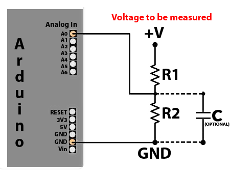
Use a 1MΩ (R1) and 470KΩ (R2) resistor in series, connected to the positive terminal on the battery and ground and then connected the tap point to the A0 input on the CPU.
The tap point could be bypassed with a 0.1 uF capacitor (connected in parallel with R2) to keep the noise level low, at this otherwise high impedance point.
The ADC is set to use the internal reference value of 1.1V - so Vmax at ADCmax = 1.1*(16+4703)/4703 = 3.44V
The battery power value must be converted to a percentage compatible with your Controller.
See the following example on how to measure battery level on A0 and report it to the Controller.
/*
 * The MySensors Arduino library handles the wireless radio link and protocol
 * between your home built sensors/actuators and HA controller of choice.
 * The sensors forms a self healing radio network with optional repeaters. Each
 * repeater and gateway builds a routing tables in EEPROM which keeps track of the
 * network topology allowing messages to be routed to nodes.
 *
 * Created by Henrik Ekblad <[email protected]>
 * Copyright (C) 2013-2019 Sensnology AB
 * Full contributor list: https://github.com/mysensors/MySensors/graphs/contributors
 *
 * Documentation: http://www.mysensors.org
 * Support Forum: http://forum.mysensors.org
 *
 * This program is free software; you can redistribute it and/or
 * modify it under the terms of the GNU General Public License
 * version 2 as published by the Free Software Foundation.
 *
 *******************************
 *
 * DESCRIPTION
 *
 * This is an example that demonstrates how to report the battery level for a sensor
 * Instructions for measuring battery capacity on A0 are available here:
 * http://www.mysensors.org/build/battery
 *
 */


// Enable debug prints to serial monitor
#define MY_DEBUG

// Enable and select radio type attached
#define MY_RADIO_RF24
//#define MY_RADIO_NRF5_ESB
//#define MY_RADIO_RFM69
//#define MY_RADIO_RFM95

#include <MySensors.h>

int BATTERY_SENSE_PIN = A0;  // select the input pin for the battery sense point

uint32_t SLEEP_TIME = 900000;  // sleep time between reads (seconds * 1000 milliseconds)
int oldBatteryPcnt = 0;

void setup()
{
    // use the 1.1 V internal reference
#if defined(__AVR_ATmega2560__)
    analogReference(INTERNAL1V1);
#else
    analogReference(INTERNAL);
#endif
}

void presentation()
{
    // Send the sketch version information to the gateway and Controller
    sendSketchInfo("Battery Meter", "1.0");
}

void loop()
{
    // get the battery Voltage
    int sensorValue = analogRead(BATTERY_SENSE_PIN);
#ifdef MY_DEBUG
    Serial.println(sensorValue);
#endif

    // 1M, 470K divider across battery and using internal ADC ref of 1.1V
    // Sense point is bypassed with 0.1 uF cap to reduce noise at that point
    // ((1e6+470e3)/470e3)*1.1 = Vmax = 3.44 Volts
    // 3.44/1023 = Volts per bit = 0.003363075

    int batteryPcnt = sensorValue / 10;

#ifdef MY_DEBUG
    float batteryV  = sensorValue * 0.003363075;
    Serial.print("Battery Voltage: ");
    Serial.print(batteryV);
    Serial.println(" V");

    Serial.print("Battery percent: ");
    Serial.print(batteryPcnt);
    Serial.println(" %");
#endif

    if (oldBatteryPcnt != batteryPcnt) {
        // Power up radio after sleep
        sendBatteryLevel(batteryPcnt);
        oldBatteryPcnt = batteryPcnt;
    }
    sleep(SLEEP_TIME);
}
Radio Power consumption
Measured using nRF24 Doctor v1.2 (ref https://forum.mysensors.org/topic/9178/nrf24doctor), nRF24 Doctor and gateway located next to each other.
| Radio | Module | Tx Min/Max [mA] | Rx [mA] | Sleep [uA] | Link |
|---|---|---|---|---|---|
| nRF24L01+ | EByte E01-ML01D | 6.5 / 11.7 | 11.8 | 0.75 | https://www.aliexpress.com/item/32803704874.html |
| nRF24L01+ | Nordic nRF24L01+-REFMOD (PCB antenna/HC49 crystal) | 7.0 / 11.7 | 12.2 | 0.98 | end-of-life |
| nRF24L01+ | No-name, No-ack ok | 6.8 / 11.7 | 12.0 | 0.94 | unknown |
| nRF24L01+ | No-name, No-ack inverted | 11.6 / 21.5 | 13.7 | 1.85 | unknown |
| nRF24L01+ | No-name, SMD castellated | 11.7 / 23.9 | 13.7 | 2.02 | https://www.aliexpress.com/item/32642004648.html (likely) |
| nRF24L01+ PA+LNA | EByte E01-ML01DP5 | 32.7 / 135.0 | 19.3 | 0.75 | https://www.aliexpress.com/item/32638720689.html |
| nRF24L01+ PA+LNA | No-name | 37.1 / 177.1 | 13.7 | 1.16 | unknown |
Battery self-discharge
MySensors nodes can run for many years of battery. But some battery types have a high self-discharge; so high that the self-discharge is the dominating factor. Therefore, as a general rule, do not use rechargeable batteries for any node where you want long battery life.
As an example, Ni-MH batteries often have a self-discharge of ~30% per month. Li-ion batteries are better, but still self-discharge at 2-4% per month. Self-discharge rate varies depending on which chemistry the battery is based on. See wikipedia for a list.
More information
https://forum.mysensors.org/topic/2067/my-slim-2aa-battery-node