
The MySensors api handles most of the commuication in the background without much inferference needed from the sketch programmer. Let's start off with a little Sensor example.
Sensor Nodes
To create the Arduino program (also known as sketch) that reports sensor data over the air you only need to write a few lines of code. In the following example we assume you have a RF24 radio attached to the arduino and want to send some door status:
#define MY_RADIO_RF24

#include <MySensors.h>

#define OPEN 1
#define CLOSE 0
#define CHILD_ID 1

MyMessage msg(CHILD_ID, V_TRIPPED);

uint8_t value = OPEN;

void presentation()
{
  present(CHILD_ID, S_DOOR);
}

void loop()
{
  value = value == OPEN ? CLOSE : OPEN;
  send(msg.set(value));
  sleep(10000);
}
Ok! So, what is happening here?
Initialization
The MySensors library is automatically started and presents the node.
If this is the first time the node is started it will fetch a unique node-id from the controller.
Once an id has been received from the controller it will be saved in the Arduino's static EEPROM memory. The id is automatically read from EEPROM each time the Sensor node resets or powers-up.
The initialization also determines the shortest network path to the gateway.
In this example the #define MY_RADIO_RF24 determines which radio type you use.
Presentation
Your sensor must first present itself to the controller. The presentation is a hint to allow controller prepare for the sensor data that eventually will come. This is done by calling present(child-sensor-id,sensor-type)
sensor-type The list of supported sensor types is constantly growing. For a more in-depth sensor type explanation, refer to the sensor type tables.
All present() calls should be placed in the
typedef enum {
    S_DOOR, S_MOTION, S_SMOKE, S_LIGHT, S_DIMMER, S_COVER, S_TEMP, ...
} sensor;
child-sensor-id Each radio node can report data for up to 254 different child sensors. You are free to choose the child id yourself. You should avoid using child-id 255 because it is used for things like sending in battery level and other (protocol internal) node specific information.
Sending Data introduction
To send data you have to create a MyMessage container to hold the information. Declaring a container looks like this:
MyMessage msg(child-sensor-id, variable-type);
In the loop() method of the example above we do the actual sending by calling send(msg.set(payload)). This is where the sensor data is transferred to the controller (or some other destination).
child-sensor-id This is where you specify the child sensor that's reporting the data. In the example we only have one child sensor so we pick 0.
variable-type When sending data to the controller you must specify what type of data you report. We call this the variable type. Often the sensor type and variable type is almost the same but there are a few sensors that report more than one variable type-value. For example; Power meters could report both the accumulated KWH and the current WATTAGE. The list of variable types is also growing. You can read the variable type table for more details.
typedef enum {
    V_TEMP, V_HUM, V_LIGHT, V_DIMMER, V_PRESSURE, V_FORECAST, V_RAIN, ...
} variableType;
You will always find the most recent list of supported sensor and variables-types in MyMessage.h on GitHub:
GitHub | MyMessage.h
The above example was intentionally simplistic and pointless because it only alternates OPEN/CLOSE value every 10 seconds. However, it should help you understand how to write a sensor sketch. There are plenty of more advanced examples here on MySensors if you enjoy copy-paste programming ;).
Create Repeating Nodes
If you live in a Faraday's cage or a huge mansion you might need a few repeater nodes to cover the full area. This is when the build-in repeater functionality comes in handy.
To turn a node into a repeater, you'll have to remember a couple of things:
Enable repeater-mode by defining the following at the top of the sketch:
#define MY_REPEATER_FEATUREKeep node awake all time (no sleeping!). This means a repeater can't be battery-powered.
The node must be able to process incoming messages (no long-running loops!). If you must run a loop, call wait() often.
Configuration
The configuration of the sketch is a very important step when building a MySensors node. It enables/disables features of the core at compile time and can be done directly in the sketch source using #define-statements.
The configuration file MyConfig.h contains many default values for the configuration value. It's pretty well documented and you can have a look at it here.

/*
 * The MySensors Arduino library handles the wireless radio link and protocol
 * between your home built sensors/actuators and HA controller of choice.
 * The sensors forms a self healing radio network with optional repeaters. Each
 * repeater and gateway builds a routing tables in RAM or EEPROM which keeps track of the
 * network topology allowing messages to be routed to nodes.
 *
 * Created by Henrik Ekblad <[email protected]>
 * Copyright (C) 2013-2019 Sensnology AB
 * Full contributor list: https://github.com/mysensors/MySensors/graphs/contributors
 *
 * Documentation: http://www.mysensors.org
 * Support Forum: http://forum.mysensors.org
 *
 * This program is free software; you can redistribute it and/or
 * modify it under the terms of the GNU General Public License
 * version 2 as published by the Free Software Foundation.
 */

/**
 * @file MyConfig.h
 * @ingroup MyConfigGrp
 * @brief MySensors specific configuration flags.
 * @{
 * Set these in your sketch before including MySensors.h to customize the library to your needs.
 * If the sketch does not define these flags, they will get default values where applicable.
 */
#ifndef MyConfig_h
#define MyConfig_h

/**
 * @defgroup SerialDebugGrpPub Serial and debugging
 * @ingroup MyConfigGrp
 * @brief These options control serial and debugging features and functionalities in the library.
 * @{
 */

/**
 * @def MY_DEBUG
 * @brief Define MY_DEBUG to show debug prints.
 *
 * This option will add a lot to the size of the final sketch but is helpful to see what is actually
 * is happening during development.
 *
 * @note Values in parenthesis indicate default values which will be used if you have not defined
 * the flag in your sketch.
 */
//#define MY_DEBUG

/**
 * @def MY_DEBUGDEVICE
 * @brief Define MY_DEBUGDEVICE to redirect debug prints.
 *
 * If defined, MY_DEBUGDEVICE replaces MY_SERIALDEVICE for the purpose
 * of printing debug messages.  This only applies to debugging.
 *
 * The intent is to provide the ability to send debugging messages
 * out a different serial port than what is being used for
 * communication between nodes or from gateway to controller when
 * this communication uses a serial interface.  This assumes that
 * the MY_DEBUGDEVICE serial interface already exists. It can be a
 * hardware serial device or a software serial device.
 */
//#define MY_DEBUGDEVICE

/**
 * @def MY_DEBUG_OTA
 * @brief Define MY_DEBUG_OTA to (nodeID) to redirect debug prints to given node ID
 *
 * Example: @code #define MY_DEBUG_OTA (0) @endcode will redirect debug prints to node ID 0.
 *
 * With this option debugging messages over serial are disabled. It's not possible to send debug
 * messages generated by the radio. All other debug messages redirected to the given Node ID.
 * The debug messages are sent without signing.
 *
 * This function allocates some additional memory for radio packet preparation and buffering.
 * Debug messages are sent to child ID 255 (NODE_SENSOR_ID) as I_LOG_MESSAGE type.
 *
 * You have to enable the @ref MY_OTA_LOG_RECEIVER_FEATURE on the target node.
 * Look into the LogOTAGateway and LogOTANode examples.
 *
 * The output buffer can be configured via @ref MY_SERIAL_OUTPUT_SIZE
 * Transport related debugging is disabled when MY_DEBUG_OTA is enabled.
 *
 */
//#define MY_DEBUG_OTA (0)

/**
 * @def MY_DEBUG_OTA_DISABLE_ECHO
 * @brief Define MY_DEBUG_OTA_DISABLE_ECHO to send messages without requesting the
 * destination to echo the message.
 *
 * This option reduces the latency added by OTA debug messages by sending packages
 * only once. You can loose debug messages.
 *
 */
//#define MY_DEBUG_OTA_DISABLE_ECHO
#if defined(MY_DEBUG_OTA_DISABLE_ACK) && !defined(DOXYGEN)
#warning MY_DEBUG_OTA_DISABLE_ACK is deprecated, please use MY_DEBUG_OTA_DISABLE_ECHO instead
#define MY_DEBUG_OTA_DISABLE_ECHO
#endif

/**
 * @def MY_OTA_LOG_RECEIVER_FEATURE
 * @brief Define this to enable printing of OTA logs.
 *
 * This option requires additional memory for buffering. The buffer size can be configured
 * via MY_SERIAL_OUTPUT_SIZE.
 */
//#define MY_OTA_LOG_RECEIVER_FEATURE

/**
 * @def MY_OTA_LOG_SENDER_FEATURE
 * @brief Define this to enable printing of OTA logs.
 *
 * This option requires additional memory for buffering. The buffer size can be configured
 * via MY_SERIAL_OUTPUT_SIZE.
 */
//#define MY_OTA_LOG_SENDER_FEATURE

/**
 * @def MY_SPECIAL_DEBUG
 * @brief Define MY_SPECIAL_DEBUG to enable support for I_DEBUG messages.
 *
 * I_DEBUG messages are sent from the controller to the node, which responds with the requested
 * data. The request can be one of the following:
 * - 'R': routing info (only repeaters): received msg XXYY (as stream), where XX is the node and YY
 *   the routing node
 * - 'V': CPU voltage
 * - 'F': CPU frequency
 * - 'M': free memory
 * - 'E': clear MySensors EEPROM area and reboot (i.e. "factory" reset)
 */
//#define MY_SPECIAL_DEBUG

/**
 * @def MY_DISABLED_SERIAL
 * @brief Define MY_DISABLED_SERIAL if you want to use the UART TX/RX pins as normal I/O pins.
 *
 * @note When defined, if you want to use the pins as a UART, you need to handle initialization and
 * configuration yourself.
 */
//#define MY_DISABLED_SERIAL

/**
 * @def MY_SPLASH_SCREEN_DISABLED
 * @ingroup memorysavings
 * @brief If defined, will disable the MySensors splash screen.
 *
 * @note This saves 120 bytes of flash.
 */
//#define MY_SPLASH_SCREEN_DISABLED

/**
 * @def MY_BAUD_RATE
 * @brief Serial output baud rate (debug prints and serial gateway speed).
 *
 * The baud rate configured here must match the baud rate at the "other" end.
 *
 * @warning Depending on your target device and clock speed, certain baud rates might not work well.
 */
#ifndef MY_BAUD_RATE
#define MY_BAUD_RATE (115200ul)
#endif

/**
 * @def MY_SERIAL_OUTPUT_SIZE
 * @brief Maximum characters for serial output.
 *
 * If you are running extremely low on memory, reducing this size might just save your day.
 */
#ifndef MY_SERIAL_OUTPUT_SIZE
#define MY_SERIAL_OUTPUT_SIZE (120u)
#endif
/** @}*/ // End of SerialDebugGrpPub group

/**
 * @def MY_DEBUG_VERBOSE_OTA_UPDATE
 * @brief Define this for verbose debug prints related to FOTA updates.
 */
//#define MY_DEBUG_VERBOSE_OTA_UPDATE

/**
 * @def MY_OTA_USE_I2C_EEPROM
 * @brief Define this if you want I2C EEPROM instead
 * of a SPI flash. Used EEPROM needs to be large enough, an 24(L)C256 will do as minimum.
 * HW I2C assumed. This will exclude the SPI flash code.
 * Note that you also need an updated DualOptiboot supporting I2C EEPROM!
 */
//#define MY_OTA_USE_I2C_EEPROM

#ifdef MY_OTA_USE_I2C_EEPROM
// I2C address of EEPROM. Wire will shift this left, i.e. 0x50->0xA0
#ifndef MY_OTA_I2C_ADDR
#define MY_OTA_I2C_ADDR        0x50
#endif
#endif


/**
 * @defgroup TransportSettingGrpPub Transport selection
 * @ingroup MyConfigGrp
 * @brief These options control what transport type to use and various transport specific customisations.
 * @{
 */


/**
 * @defgroup RS485SettingGrpPub RS485
 * @ingroup TransportSettingGrpPub
 * @brief These options are specific to the RS485 wired transport.
 * @{
 */

/**
 * @def MY_RS485
 * @brief Define this to use the RS485 wired transport for sensor network communication.
 */
//#define MY_RS485

/**
 * @def MY_RS485_BAUD_RATE
 * @brief The RS485 BAUD rate.
 */
#ifndef MY_RS485_BAUD_RATE
#define MY_RS485_BAUD_RATE (9600)
#endif

/**
 * @def MY_RS485_MAX_MESSAGE_LENGTH
 * @brief The maximum message length used for RS485.
 */
#ifndef MY_RS485_MAX_MESSAGE_LENGTH
#define MY_RS485_MAX_MESSAGE_LENGTH (40)
#endif

/**
 * @def MY_RS485_SOH_COUNT
 * @brief Use this in case of collisions on the bus. 3 might be a good setting.
 */
#ifndef MY_RS485_SOH_COUNT
#define MY_RS485_SOH_COUNT (1)
#endif


/**
 * @def MY_RS485_DE_PIN
 * @brief RS485 driver enable pin.
 */
//#define MY_RS485_DE_PIN (2)

/**
 * @def MY_RS485_DE_INVERSE
 * @brief Define this if RS485 driver enable pin polarity is inverted (low-active).
 */
//#define MY_RS485_DE_INVERSE

/**
 * @def MY_RS485_HWSERIAL
 * @brief Define this if RS485 is connected to a hardware serial port.
 *
 * Example: @code #define MY_RS485_HWSERIAL Serial1 @endcode
 */
//#define MY_RS485_HWSERIAL (Serial1)
/** @}*/ // End of RS485SettingGrpPub group

/**
 * @defgroup RF24SettingGrpPub RF24
 * @ingroup TransportSettingGrpPub
 * @brief These options are specific to the RF24 family of wireless transport modules.
 *
 * The following chips are supported by this driver:
 * | Vendor                   | Chip
 * |--------------------------|----------
 * | Nordic Semiconductor     | nRF24L01
 * |                          | nRF24L01+
 * | Beken Corporation        | BK2401
 * |                          | BK2421
 * |                          | BK2491
 * | Hope Microelectronics    | RFM70
 * |                          | RFM73
 * | Panchip Microelectronics | XN297
 * | Silicon Labs(?)          | SI24R1
 * @{
 */

// legacy - remove for 3.0.0
/**
* @def MY_RADIO_NRF24
* @brief Define this to use a RF24-based radio transport for sensor network communication.
* @deprecated This flag is deprecated and replaced by @ref MY_RADIO_RF24
*/
#ifdef MY_RADIO_NRF24
#warning MY_RADIO_NRF24 is deprecated, use MY_RADIO_RF24 instead.
#undef MY_RADIO_NRF24
#define MY_RADIO_RF24
#endif

/**
 * @def MY_RADIO_RF24
 * @brief Define this to use a RF24-based radio transport for sensor network communication.
 */
//#define MY_RADIO_RF24

/**
 * @def MY_RF24_ENABLE_ENCRYPTION
 * @brief Define this to enable software based %AES encryption.
 *
 * All nodes and gateway must have this enabled, and all must be personalized with the same %AES
 * key.
 * @see @ref personalization
 *
 * @warning This driver always sets the initialization vector to 0 so encryption is weak.
 */
//#define MY_RF24_ENABLE_ENCRYPTION

/**
 * @def MY_DEBUG_VERBOSE_RF24
 * @brief Define this for verbose debug prints related to the RF24 driver.
 */
//#define MY_DEBUG_VERBOSE_RF24

/**
 * @def MY_RF24_SPI_SPEED
 * @brief Define this if you need to run the SPI clock at a different frequency than the default.
 *
 * Default nRF24L01+ SPI speed, 2MHz should be safe for nRF24L01+ clones.
 */
#ifndef MY_RF24_SPI_SPEED
#define MY_RF24_SPI_SPEED (2*1000000ul)
#endif

/**
 * @def MY_RF24_CE_PIN
 * @brief Define this to change the chip enable pin from the default.
 */
#ifndef MY_RF24_CE_PIN
#define MY_RF24_CE_PIN (DEFAULT_RF24_CE_PIN)
#endif

/**
 * @def MY_RF24_CS_PIN
 * @brief Define this to change the chip select pin from the default.
 */
#ifndef MY_RF24_CS_PIN
#define MY_RF24_CS_PIN (DEFAULT_RF24_CS_PIN)
#endif

/**
 * @def MY_RF24_IRQ_PIN
 * @brief Define this to use the IRQ pin of the RF24 module (optional).
 */
//#define MY_RF24_IRQ_PIN (2)

/**
 * @def MY_RF24_POWER_PIN
 * @brief Define this to use the RF24 power pin (optional).
 */
//#define MY_RF24_POWER_PIN (3)

/**
 * @def MY_RX_MESSAGE_BUFFER_FEATURE
 * @brief This enables the receiving buffer feature.
 *
 * This feature is currently not supported for anything but RF24.
 * Require @ref MY_RF24_IRQ_PIN to be set.
 *
 * Note: Not supported on ESP8266, ESP32, STM32, nRF5 and sketches
 * that use SoftSPI. See below issue for details
 * https://github.com/mysensors/MySensors/issues/1128
 */
//#define MY_RX_MESSAGE_BUFFER_FEATURE

/**
 * @def MY_RX_MESSAGE_BUFFER_SIZE
 * @brief Define this to change the incoming message buffer size from the default.
 *
 * Require @ref MY_RX_MESSAGE_BUFFER_FEATURE to be set.
 */
#ifdef MY_RX_MESSAGE_BUFFER_FEATURE
#ifndef MY_RX_MESSAGE_BUFFER_SIZE
#define MY_RX_MESSAGE_BUFFER_SIZE (20)
#endif
#endif

/**
 * @def MY_RF24_PA_LEVEL
 * @brief Default RF24 PA level. Override in sketch if needed.
 *
 * - RF24_PA_MIN = -18dBm
 * - RF24_PA_LOW = -12dBm
 * - RF24_PA_HIGH = -6dBm
 * - RF24_PA_MAX = 0dBm
 */
#ifndef MY_RF24_PA_LEVEL
#define MY_RF24_PA_LEVEL (RF24_PA_HIGH)
#endif

/**
 * @def MY_RF24_CHANNEL
 * @brief RF channel for the sensor net, 0-125.
 *
 * Frequencies: 2400 Mhz - 2525 Mhz
 *
 * Channels: 126
 * @see https://www.nordicsemi.com/eng/nordic/download_resource/8765/2/42877161/2726
 *
 * - 0 => 2400 Mhz (RF24 channel 1)
 * - 1 => 2401 Mhz (RF24 channel 2)
 * - 76 => 2476 Mhz (RF24 channel 77)
 * - 83 => 2483 Mhz (RF24 channel 84)
 * - 124 => 2524 Mhz (RF24 channel 125)
 * - 125 => 2525 Mhz (RF24 channel 126)
 *
 * In some countries there might be limitations, in Germany for example only the range
 * 2400,0 - 2483,5 Mhz is allowed.
 * @see http://www.bundesnetzagentur.de/SharedDocs/Downloads/DE/Sachgebiete/Telekommunikation/Unternehmen_Institutionen/Frequenzen/Allgemeinzuteilungen/2013_10_WLAN_2,4GHz_pdf.pdf
 */
#ifndef MY_RF24_CHANNEL
#define MY_RF24_CHANNEL (76)
#endif

/**
 * @def MY_RF24_DATARATE
 * @brief RF24 data rate.
 *
 * - RF24_250KBPS for 250kbs
 * - RF24_1MBPS for 1Mbps
 * - RF24_2MBPS for 2Mbps.
 *
 * @note nRF24L01, BK2401, BK2421, BK2491 and XN297 does not support RF24_250KBPS
 * @note BK2401 does not support RF24_2MBPS
 */
#ifndef MY_RF24_DATARATE
#define MY_RF24_DATARATE (RF24_250KBPS)
#endif

/**
 * @def MY_RF24_BASE_RADIO_ID
 * @brief RF24 radio network identifier.
 *
 * This acts as base value for sensor nodeId addresses. Change this (or channel) if you have more
 * than one sensor network.
 */
#ifndef MY_RF24_BASE_RADIO_ID
#define MY_RF24_BASE_RADIO_ID 0x00,0xFC,0xE1,0xA8,0xA8
#endif

/**
 * @def MY_RF24_ADDR_WIDTH
 * @brief RF24 base address width.
 */
#ifndef MY_RF24_ADDR_WIDTH
#define MY_RF24_ADDR_WIDTH (5)
#endif
/** @}*/ // End of RF24SettingGrpPub group

/**
 * @defgroup NRF5SettingGrpPub nRF5
 * @ingroup TransportSettingGrpPub
 * @brief These options are specific to the nRF5 (with Enhanced ShockBurst) family of wireless
 * transport modules.
 *
 * The nRF5 driver is OTA compatible with the RF24 driver.
 *
 * The following chips are supported by this driver:
 * - nRF51x22
 * - nRF52822
 *
 * @{
 */

/**
 * @def MY_RADIO_NRF5_ESB
 * @brief Define this to use nRF5 based radios for sensor network communication.
 *
 * @see ARDUINO_ARCH_NRF5
 */
//#define MY_RADIO_NRF5_ESB

/**
 * @def MY_NRF5_ESB_ENABLE_ENCRYPTION
 * @brief Define this to enable software based (RF24 compatible) %AES encryption.
 *
 * All nodes and gateway must have this enabled, and all must be personalized with the same %AES
 * key.
 * @see @ref personalization
 *
 * @warning This driver always sets the initialization vector to 0 so encryption is weak.
 */
//#define MY_NRF5_ESB_ENABLE_ENCRYPTION

/**
 * @def MY_DEBUG_VERBOSE_NRF5_ESB
 * @brief Define this for verbose debug prints related to the nRF5 driver.
 */
//#define MY_DEBUG_VERBOSE_NRF5_ESB

/**
 * @def MY_NRF5_ESB_PA_LEVEL
 * @brief Default nRF5 PA level. Override in sketch if needed.
 *
 * - NRF5_PA_MIN = -40dBm
 * - NRF5_PA_LOW = -16dBm
 * - NRF5_PA_HIGH = 0dBm
 * - NRF5_PA_MAX = 4dBm
 */
#ifndef MY_NRF5_ESB_PA_LEVEL
#define MY_NRF5_ESB_PA_LEVEL (NRF5_PA_MAX)
#endif

/**
 * @def MY_NRF5_ESB_CHANNEL
 * @brief RF channel for the sensor net, 0-125.
 *
 * Frequencies: 2400 Mhz - 2525 Mhz
 *
 * Channels: 126
 * @see https://www.nordicsemi.com/eng/nordic/download_resource/8765/2/42877161/2726
 *
 * - 0 => 2400 Mhz (RF24 channel 1)
 * - 1 => 2401 Mhz (RF24 channel 2)
 * - 76 => 2476 Mhz (RF24 channel 77)
 * - 83 => 2483 Mhz (RF24 channel 84)
 * - 124 => 2524 Mhz (RF24 channel 125)
 * - 125 => 2525 Mhz (RF24 channel 126)
 *
 * In some countries there might be limitations, in Germany for example only the range
 * 2400,0 - 2483,5 Mhz is allowed.
 * @see http://www.bundesnetzagentur.de/SharedDocs/Downloads/DE/Sachgebiete/Telekommunikation/Unternehmen_Institutionen/Frequenzen/Allgemeinzuteilungen/2013_10_WLAN_2,4GHz_pdf.pdf
 */
#ifndef MY_NRF5_ESB_CHANNEL
#define MY_NRF5_ESB_CHANNEL (76)
#endif

/**
 * @def MY_NRF5_ESB_MODE
 * @brief nRF5 mode.
 *
 * - NRF5_250KBPS for 250kbs (Deprecated)
 * - NRF5_1MBPS for 1Mbps
 * - NRF5_2MBPS for 2Mbps.
 * - NRF5_BLE_1MBPS for 1Mbps BLE modulation
 */
#ifndef MY_NRF5_ESB_MODE
#define MY_NRF5_ESB_MODE (NRF5_250KBPS)
#endif

/**
 * @def MY_NRF5_ESB_BASE_RADIO_ID
 * @brief nRF5 radio network identifier.
 *
 * This acts as base value for sensor nodeId addresses. Change this (or channel) if you have more
 * than one sensor network.
 */
#ifndef MY_NRF5_ESB_BASE_RADIO_ID
#define MY_NRF5_ESB_BASE_RADIO_ID 0x00, 0xFC, 0xE1, 0xA8, 0xA8
#endif

/**
 * @def MY_NRF5_ESB_ADDR_WIDTH
 * @brief nRF5 base address width.
 */
#ifndef MY_NRF5_ESB_ADDR_WIDTH
#define MY_NRF5_ESB_ADDR_WIDTH (5)
#endif

/**
 * @def MY_NRF5_ESB_RX_BUFFER_SIZE
 * @brief Declare the amount of incoming messages that can be buffered at driver level.
 */
#ifndef MY_NRF5_ESB_RX_BUFFER_SIZE
#define MY_NRF5_ESB_RX_BUFFER_SIZE (20)
#endif

/**
 * @def MY_NRF5_ESB_REVERSE_ACK_TX
 * @brief Switch to SI24R1 or faked nRF24L01+ compatible ACK mode. ACK bit is reversed on TX side.
 */
//#define MY_NRF5_ESB_REVERSE_ACK_TX

/**
 * @def MY_NRF5_ESB_REVERSE_ACK_RX
 * @brief Switch to SI24R1 or faked nRF24L01+ compatible ACK mode. ACK bit is reversed on RX side.
 */
//#define MY_NRF5_ESB_REVERSE_ACK_RX
/** @}*/ // End of NRF5SettingGrpPub group

/**
 * @defgroup RFM69SettingGrpPub RFM69
 * @ingroup TransportSettingGrpPub
 * @brief These options are specific to the %RFM69 family of wireless transport modules.
 *
 * The following chips are supported by this driver:
 * - Semtech sx1231
 *
 * If using the HW variant of the %RFM69 module, define @ref MY_IS_RFM69HW.
 * @{
 */

/**
 * @def MY_RADIO_RFM69
 * @brief Define this to use %RFM69 based radios for sensor network communication.
 */
//#define MY_RADIO_RFM69

/**
 * @def MY_DEBUG_VERBOSE_RFM69
 * @brief Define this for verbose debug prints related to the %RFM69 driver.
 */
//#define MY_DEBUG_VERBOSE_RFM69

/**
 * @def MY_DEBUG_VERBOSE_RFM69_REGISTERS
 * @brief Define this for verbose dumping of the %RFM69 registers.
 */
//#define MY_DEBUG_VERBOSE_RFM69_REGISTERS

/**
 * @def MY_RFM69_NEW_DRIVER
 * @brief Define this to enable the improved %RFM69 driver.
 *
 * @note  This driver is not compatible with the old (=default) %RFM69 driver.
 */
//#define MY_RFM69_NEW_DRIVER

/**
 * @def MY_RFM69_FREQUENCY
 * @brief The frequency to use.
 *
 * - RFM69_315MHZ
 * - RFM69_433MHZ
 * - RFM69_865MHZ
 * - RFM69_868MHZ
 * - RFM69_915MHZ
 * - Custom frequency in Hz (new %RFM69 driver only)
 * @see MY_RFM69_NEW_DRIVER
 *
 * This must match the hardware version of the %RFM69 radio.
 * Additional information: https://en.wikipedia.org/wiki/Short_Range_Devices
 */
#ifndef MY_RFM69_FREQUENCY
#define MY_RFM69_FREQUENCY (RFM69_868MHZ)
#endif

/**
 * @def MY_IS_RFM69HW
 * @brief Define this if you are using the RFM69HW model.
 */
//#define MY_IS_RFM69HW

/**
 * @def MY_RFM69HW
 * @brief Set to true if @ref MY_IS_RFM69HW is set.
 *
 * @todo Mark this internals
 */
#ifdef MY_IS_RFM69HW
#define MY_RFM69HW true
#else
#define MY_RFM69HW false
#endif

/**
 * @def MY_RFM69_TX_POWER_DBM
 * @brief Set TX power level, default 5dBm (overridden if ATC mode enabled).
 */
#ifndef MY_RFM69_TX_POWER_DBM
#define MY_RFM69_TX_POWER_DBM (5)
#endif

/**
 * @def MY_RFM69_ATC_TARGET_RSSI_DBM
 * @brief Target RSSI level (in dBm) for %RFM69 ATC mode.
 */
#ifndef MY_RFM69_ATC_TARGET_RSSI_DBM
#define MY_RFM69_ATC_TARGET_RSSI_DBM (-80)
#endif

/**
 * @def MY_RFM69_ATC_MODE_DISABLED
 * @brief Define to disable ATC mode of %RFM69 driver.
 */
//#define MY_RFM69_ATC_MODE_DISABLED

/**
 * @def MY_RFM69_MAX_POWER_LEVEL_DBM
 * @brief Set max TX power in dBm if local legislation requires this
 *
 * - 1mW = 0dBm
 * - 10mW = 10dBm
 * - 25mW = 14dBm
 * - 100mW = 20dBm
 *
 * See here: https://en.wikipedia.org/wiki/Short_Range_Devices
 */
//#define MY_RFM69_MAX_POWER_LEVEL_DBM (10u)

/**
 * @def MY_RFM69_NETWORKID
 * @brief %RFM69 Network ID. Use the same for all nodes that will talk to each other.
 */
#ifndef MY_RFM69_NETWORKID
#define MY_RFM69_NETWORKID (100)
#endif

/**
 * @def MY_RFM69_RST_PIN
 * @brief Define this to use the %RFM69 reset pin (optional).
 */
//#define MY_RFM69_RST_PIN (9)

#ifdef MY_RF69_RESET
#warning MY_RF69_RESET is depreciated, please use MY_RFM69_RST_PIN instead.
#define MY_RFM69_RST_PIN MY_RF69_RESET
#endif

/**
 * @def MY_RFM69_POWER_PIN
 * @brief Define this to use the %RFM69 power pin (optional).
 */
//#define MY_RFM69_POWER_PIN (3)

/**
 * @def MY_RFM69_IRQ_PIN
 * @brief Define this to override the default %RFM69 IRQ pin assignment.
 */
#ifndef MY_RFM69_IRQ_PIN
#ifdef MY_RF69_IRQ_PIN
#warning MY_RF69_IRQ_PIN is depreciated, please use MY_RFM69_IRQ_PIN instead.
#define MY_RFM69_IRQ_PIN MY_RF69_IRQ_PIN
#else
#define MY_RFM69_IRQ_PIN DEFAULT_RFM69_IRQ_PIN
#endif
#endif

/**
 * @def MY_RFM69_IRQ_NUM
 * @brief %RFM69 IRQ number.
 */
#ifndef MY_RFM69_IRQ_NUM
#ifdef MY_RF69_IRQ_NUM
#warning MY_RF69_IRQ_NUM is depreciated, please use MY_RFM69_IRQ_NUM instead.
#define MY_RFM69_IRQ_NUM MY_RF69_IRQ_NUM
#else
#define MY_RFM69_IRQ_NUM digitalPinToInterrupt(MY_RFM69_IRQ_PIN)
#endif
#endif

/**
 * @def MY_RFM69_CS_PIN
 * @brief %RFM69 SPI chip select pin.
 */
#ifndef MY_RFM69_CS_PIN
#ifdef MY_RF69_SPI_CS
#warning MY_RF69_SPI_CS is depreciated, please use MY_RFM69_CS_PIN instead.
#define MY_RFM69_CS_PIN MY_RF69_SPI_CS
#else
#define MY_RFM69_CS_PIN DEFAULT_RFM69_CS_PIN
#endif
#endif

/**
 * @def MY_RFM69_SPI_SPEED
 * @brief Set to overrule default RFM69 SPI speed.
 */
#ifndef MY_RFM69_SPI_SPEED
#define MY_RFM69_SPI_SPEED (4*1000000ul)    // datasheet says 10Mhz max.
#endif

/**
 * @def MY_RFM69_ENABLE_ENCRYPTION
 * @brief Define this to enable %AES encryption in the %RFM69 module.
 *
 * All nodes and gateway must have this enabled, and all must be personalized with the same %AES
 * key.
 * @see @ref personalization
 */
//#define MY_RFM69_ENABLE_ENCRYPTION

/**
 * @def MY_RFM69_MODEM_CONFIGURATION
 * @brief %RFM69 modem configuration, default is %RFM69_FSK_BR55_5_FD50
 *
 * | Configuration           | Modulation (xxx) | Bit rate | FD     | RXBW     | Additional settings
 * |-------------------------|------------------|----------|--------|----------|---------------------------
 * | RFM69_xxx_BR2_FD5       | FSK/GFSK/OOK     | 2000     | 5000   | 111_24_4 | Whitening
 * | RFM69_xxx_BR2_4_FD4_8   | FSK/GFSK/OOK     | 2400     | 4800   | 111_24_4 | Whitening
 * | RFM69_xxx_BR4_8_FD9_6   | FSK/GFSK/OOK     | 4800     | 9600   | 111_24_4 | Whitening
 * | RFM69_xxx_BR9_6_FD19_2  | FSK/GFSK/OOK     | 9600     | 19200  | 111_24_4 | Whitening
 * | RFM69_xxx_BR19_2_FD38_4 | FSK/GFSK/OOK     | 19200    | 38400  | 111_24_3 | Whitening
 * | RFM69_xxx_BR38_4_FD76_8 | FSK/GFSK/OOK     | 38400    | 76800  | 111_24_2 | Whitening
 * | RFM69_xxx_BR55_5_FD50   | FSK/GFSK/OOK     | 55555    | 50000  | 111_16_2 | Whitening
 * | RFM69_xxx_BR57_6_FD120  | FSK/GFSK/OOK     | 57600    | 120000 | 111_16_1 | Whitening
 * | RFM69_xxx_BR125_FD125   | FSK/GFSK/OOK     | 125000   | 125000 | 010_16_2 | Whitening
 * | RFM69_xxx_BR250_FD250   | FSK/GFSK/OOK     | 250000   | 250000 | 111_16_0 | Whitening
 *
 * https://www.semtech.com/uploads/documents/sx1231.pdf
 *
 */
//#define MY_RFM69_MODEM_CONFIGURATION (RFM69_FSK_BR55_5_FD50)


/** @}*/ // End of RFM69SettingGrpPub group

/**
 * @defgroup RFM95SettingGrpPub RFM95
 * @ingroup TransportSettingGrpPub
 * @brief These options are specific to the %RFM95 family of wireless transport modules.
 *
 * The following chips are supported by this driver:
 * - Semtech sx1276
 * @{
 */

/**
 * @def MY_RADIO_RFM95
 * @brief Define this to use RFM95 based radios for sensor network communication.
 */
//#define MY_RADIO_RFM95

/**
 * @def MY_DEBUG_VERBOSE_RFM95
 * @brief Define this for verbose debug prints related to the RFM95 driver.
 */
//#define MY_DEBUG_VERBOSE_RFM95

/**
 * @def MY_RFM95_ENABLE_ENCRYPTION
 * @brief Define this to enable software based %AES encryption.
 *
 * All nodes and gateway must have this enabled, and all must be personalized with the same %AES
 * key.
 * @see @ref personalization
 *
 * @warning This driver always sets the initialization vector to 0 so encryption is weak.
 */
//#define MY_RFM95_ENABLE_ENCRYPTION

/**
 * @def MY_RFM95_FREQUENCY
 * @brief The frequency to use.
 *
 * - RFM95_169MHZ
 * - RFM95_315MHZ
 * - RFM95_434MHZ
 * - RFM95_868MHZ
 * - RFM95_915MHZ
 * - Custom frequency in Hz
 *
 * This must match the hardware version of the RFM95 radio.
 * Additional information: https://en.wikipedia.org/wiki/Short_Range_Devices
 */
#ifndef MY_RFM95_FREQUENCY
#define MY_RFM95_FREQUENCY (RFM95_868MHZ)
#endif

/**
 * @def MY_RFM95_MODEM_CONFIGRUATION
 * @brief RFM95 modem configuration.
 *
 * BW = Bandwidth in kHz
 * CR = Error correction code
 * SF = Spreading factor, chips / symbol
 *
 * | CONFIG                 | BW    | CR  | SF   | Comment
 * |------------------------|-------|-----|------|-----------------------------
 * | RFM95_BW125CR45SF128   | 125   | 4/5 | 128  | Default, medium range
 * | RFM95_BW500CR45SF128   | 500   | 4/5 | 128  | Fast, short range
 * | RFM95_BW31_25CR48SF512 | 31.25 | 4/8 | 512  | Slow, long range
 * | RFM95_BW125CR48SF4096  | 125   | 4/8 | 4096 | Slow, long range
 *
 */
#ifndef MY_RFM95_MODEM_CONFIGRUATION
#define MY_RFM95_MODEM_CONFIGRUATION RFM95_BW125CR45SF128
#endif

/**
 * @def MY_RFM95_RST_PIN
 * @brief Define this to use the RFM95 reset pin (optional).
 */
//#define MY_RFM95_RST_PIN (9)

/**
 * @def MY_RFM95_POWER_PIN
 * @brief Define this to use the RFM95 power pin (optional).
 */
//#define MY_RFM95_POWER_PIN (3)

/**
 * @def MY_RFM95_IRQ_PIN
 * @brief Define this to use the RFM95 IRQ pin.
 */
#ifndef MY_RFM95_IRQ_PIN
#define MY_RFM95_IRQ_PIN DEFAULT_RFM95_IRQ_PIN
#endif

/**
 * @def MY_RFM95_IRQ_NUM
 * @brief RFM95 IRQ number.
 */
#ifndef MY_RFM95_IRQ_NUM
#define MY_RFM95_IRQ_NUM digitalPinToInterrupt(MY_RFM95_IRQ_PIN)
#endif

/**
 * @def MY_RFM95_CS_PIN
 * @brief RFM95 SPI chip select pin.
 */
#ifndef MY_RFM95_CS_PIN
#define MY_RFM95_CS_PIN DEFAULT_RFM95_CS_PIN
#endif

/**
 * @def MY_RFM95_SPI_SPEED
 * @brief Set to overrule default RFM95 SPI speed.
 */
#ifndef MY_RFM95_SPI_SPEED
#define MY_RFM95_SPI_SPEED (4*1000000ul)
#endif

/**
 * @def MY_RFM95_TX_POWER_DBM
 * @brief Set TX power level, default 13dBm (overridden if ATC mode enabled)
 *
 * See here https://en.wikipedia.org/wiki/Short_Range_Devices
 */
#ifndef MY_RFM95_TX_POWER_DBM
#define MY_RFM95_TX_POWER_DBM (13u)    // 20mW
#endif

/**
 * @def MY_RFM95_ATC_MODE_DISABLED
 * @brief Define to disable ATC mode of RFM95 driver.
 */
//#define MY_RFM95_ATC_MODE_DISABLED

/**
 * @def MY_RFM95_ATC_TARGET_RSSI
 * @brief Target RSSI level (in dBm) for RFM95 ATC mode
 */
#ifndef MY_RFM95_ATC_TARGET_RSSI
#define MY_RFM95_ATC_TARGET_RSSI (-70)
#endif

/**
 * @def MY_RFM95_MAX_POWER_LEVEL_DBM
 * @brief Set max TX power in dBm if local legislation requires this
 *
 * - 1mW = 0dBm
 * - 10mW = 10dBm
 * - 25mW = 14dBm
 * - 100mW = 20dBm
 *
 * See here: https://en.wikipedia.org/wiki/Short_Range_Devices
 */
//#define MY_RFM95_MAX_POWER_LEVEL_DBM (10u)

/**
 * @def MY_RFM95_TCXO
 * @brief Enable to force your radio to use an external frequency source (e.g. TCXO, if present).
 *
 * This allows for better stability using SF 9 to 12.
 */
//#define MY_RFM95_TCXO
/** @}*/ // End of RFM95SettingGrpPub group

/**
 * @defgroup SoftSpiSettingGrpPub Soft SPI
 * @ingroup TransportSettingGrpPub
 * @brief These options are specific the soft SPI driver for certain radio transport drivers.
 *
 * The following transport drivers supported by this driver:
 * - The RF24 driver @see RF24SettingGrpPub
 * - The new %RFM69 driver @see RFM69SettingGrpPub @see MY_RFM69_NEW_DRIVER
 * - The RFM95 driver @see RFM95SettingGrpPub
 * @{
 */

/**
 * @def MY_SOFTSPI
 * @brief Define this to use a software based SPI driver which allows more freedom in pin selection
 * for the (supported) radio module.
 */
//#define MY_SOFTSPI

/**
 * @def MY_SOFT_SPI_SCK_PIN
 * @brief Soft SPI SCK pin.
 */
#ifndef MY_SOFT_SPI_SCK_PIN
#define MY_SOFT_SPI_SCK_PIN (14)
#endif

/**
 * @def MY_SOFT_SPI_MISO_PIN
 * @brief Soft SPI MISO pin.
 */
#ifndef MY_SOFT_SPI_MISO_PIN
#define MY_SOFT_SPI_MISO_PIN (16)
#endif

/**
 * @def MY_SOFT_SPI_MOSI_PIN
 * @brief Soft SPI MOSI pin.
 */
#ifndef MY_SOFT_SPI_MOSI_PIN
#define MY_SOFT_SPI_MOSI_PIN (15)
#endif
/** @}*/ // End of SoftSpiSettingGrpPub group

/** @}*/ // End of TransportSettingGrpPub group

/**
 * @defgroup RoutingNodeSettingGrpPub Routing and node
 * @ingroup MyConfigGrp
 * @brief These options control message routing and node configurations.
 * @{
 */
/**
 * @def MY_DISABLE_RAM_ROUTING_TABLE_FEATURE
 * @ingroup memorysavings
 * @brief If defined, routing table will not be kept in RAM.
 * @see MY_RAM_ROUTING_TABLE_FEATURE
 */
/**
 * @def MY_RAM_ROUTING_TABLE_FEATURE
 * @brief If enabled, the routing table is kept in RAM (if memory allows) and saved in regular
 *        intervals.
 * @note Enabled by default on most platforms, but on AVR only for atmega1280, atmega1284 and
 *       atmega2560.
 * @see MY_DISABLE_RAM_ROUTING_TABLE_FEATURE
 */
#ifndef MY_DISABLE_RAM_ROUTING_TABLE_FEATURE
#define MY_RAM_ROUTING_TABLE_FEATURE
#endif

/**
 * @def MY_ROUTING_TABLE_SAVE_INTERVAL_MS
 * @brief Interval to dump content of routing table to EEPROM
 */
#ifndef MY_ROUTING_TABLE_SAVE_INTERVAL_MS
#define MY_ROUTING_TABLE_SAVE_INTERVAL_MS (30*60*1000ul)
#endif

/**
 * @def MY_REPEATER_FEATURE
 * @brief Enables repeater functionality (relays messages from other nodes)
 * @note Repeaters need to be constantly kept awake to be useful. They are therefore not suitable
 *       for battery powered operation.
 */
//#define MY_REPEATER_FEATURE

/**
 * @def MY_PASSIVE_NODE
 * @brief If enabled, the node operates fully autonomously, i.e. messages are sent without ACKing.
 *
 * @note All transport-related checks and safety-mechanisms are disabled.
 * @note Requires that @ref MY_NODE_ID is set, @ref MY_PARENT_NODE_ID and
 *       @ref MY_PARENT_NODE_IS_STATIC are optional.
 * @note Singing, registration, and OTA FW update are disabled.
 */
//#define MY_PASSIVE_NODE

/**
 * @def MY_NODE_ID
 * @brief Node id defaults to AUTO (tries to fetch id from controller).
 */
#ifndef MY_NODE_ID
#define MY_NODE_ID (AUTO)
#endif

/**
 * @def MY_PARENT_NODE_ID
 * @brief Node parent defaults to AUTO (tries to find a parent automatically).
 */
#ifndef MY_PARENT_NODE_ID
#define MY_PARENT_NODE_ID (AUTO)
#endif

/**
 * @def MY_PARENT_NODE_IS_STATIC
 * @brief Define MY_PARENT_NODE_IS_STATIC to disable fall back if parent node fails
 */
//#define MY_PARENT_NODE_IS_STATIC

/**
 * @def MY_TRANSPORT_SANITY_CHECK
 * @brief If defined, will cause node to check transport in regular intervals to detect HW issues
 *        and re-initialize in case of failure.
 * @note This feature is enabled for all repeater nodes (incl. GW)
 */
//#define MY_TRANSPORT_SANITY_CHECK

/**
 * @def MY_TRANSPORT_SANITY_CHECK_INTERVAL_MS
 * @brief Interval (in ms) for transport sanity checks
 */
#ifndef MY_TRANSPORT_SANITY_CHECK_INTERVAL_MS
#define MY_TRANSPORT_SANITY_CHECK_INTERVAL_MS (15*60*1000ul)
#endif
/**
 * @def MY_TRANSPORT_DISCOVERY_INTERVAL_MS
 * @brief This is a gateway-only feature: Interval (in ms) to issue network discovery checks
 */
#ifndef MY_TRANSPORT_DISCOVERY_INTERVAL_MS
#define MY_TRANSPORT_DISCOVERY_INTERVAL_MS (20*60*1000ul)
#endif

/**
 *@def MY_TRANSPORT_UPLINK_CHECK_DISABLED
 *@brief If defined, disables uplink check to GW during transport initialisation
 */
//#define MY_TRANSPORT_UPLINK_CHECK_DISABLED

/**
 *@def MY_TRANSPORT_MAX_TX_FAILURES
 *@brief Define to override max. consecutive TX failures until SNP is initiated
 */
//#define MY_TRANSPORT_MAX_TX_FAILURES (10u)

/**
 * @def MY_TRANSPORT_WAIT_READY_MS
 * @brief Timeout in ms until transport is ready during startup, set to 0 for no timeout
 */
#ifndef MY_TRANSPORT_WAIT_READY_MS
#define MY_TRANSPORT_WAIT_READY_MS (0)
#endif

/**
* @def MY_SIGNAL_REPORT_ENABLED
* @brief Enables signal report functionality.
* @note This feature adds ~1kB code to the sketch.
*/
//#define MY_SIGNAL_REPORT_ENABLED

/** @}*/ // End of RoutingNodeSettingGrpPub group

/**
 * @defgroup RegistrationSettingGrpPub Node registration
 * @ingroup MyConfigGrp
 * @brief These options control node registration configurations.
 * @{
 */
/**
 * @def MY_REGISTRATION_FEATURE
 * @brief If enabled, node has to register to GW/controller before being allowed to send sensor
 *        data.
 * @note Enabled by default.
 */
#define MY_REGISTRATION_FEATURE

/**
 * @def MY_REGISTRATION_RETRIES
 * @brief Number of registration retries if no reply received from GW/controller.
 */

#ifndef MY_REGISTRATION_RETRIES
#define MY_REGISTRATION_RETRIES (3u)
#endif

/**
* @def MY_REGISTRATION_DEFAULT
* @brief Node registration default - this applies if no registration response is received from
 *       controller.
*/
#define MY_REGISTRATION_DEFAULT (true)

/**
 * @def MY_REGISTRATION_CONTROLLER
 * @brief If defined, node registration request has to be handled by controller
 */
//#define MY_REGISTRATION_CONTROLLER
/** @}*/ // End of RegistrationSettingGrpPub group

/**
 * @defgroup CoreSettingGrpPub Core
 * @ingroup MyConfigGrp
 * @brief These options control the library core configurations.
 * @{
 */
/**
 * @def MY_CORE_ONLY
 * @brief Define this if you want to use core functions without loading the framework.
 */
//#define MY_CORE_ONLY

/**
 * @def MY_CORE_COMPATIBILITY_CHECK
 * @brief If defined, library compatibility is checked during node registration.
 *        Incompatible libraries are unable to send sensor data.
 */
#define MY_CORE_COMPATIBILITY_CHECK
/** @}*/ // End of CoreSettingGrpPub group

/**
 * @defgroup SleepSettingGrpPub Sleep
 * @ingroup MyConfigGrp
 * @brief These options control sleep configurations.
 * @{
 */
/**
 * @def MY_SLEEP_TRANSPORT_RECONNECT_TIMEOUT_MS
 * @brief Timeout (in ms) to re-establish link if node is send to sleep and transport is not ready.
 */
#ifndef MY_SLEEP_TRANSPORT_RECONNECT_TIMEOUT_MS
#define MY_SLEEP_TRANSPORT_RECONNECT_TIMEOUT_MS (10*1000ul)
#endif

/**
 * @def MY_SMART_SLEEP_WAIT_DURATION_MS
 * @brief The wait period (in ms) before going to sleep when using smartSleep-functions.
 *
 * This period has to be long enough for controller to be able to send out
 * potential buffered messages.
 */
#ifndef MY_SMART_SLEEP_WAIT_DURATION_MS
#define MY_SMART_SLEEP_WAIT_DURATION_MS (500ul)
#endif
/** @}*/ // End of SleepSettingGrpPub group

/**
 * @defgroup OTASettingGrpPub Over The Air firmware
 * @ingroup MyConfigGrp
 * @brief These options control OTA firmware configurations.
 * @{
 */

/**
 * @def MY_OTA_FIRMWARE_FEATURE
 * @brief Define this in sketch to allow safe over-the-air firmware updates.
 *
 * This feature requires external flash and the DualOptiBoot boot-loader.
 * @note You can still have OTA FW updates without external flash but it
 *       requires the MYSBootloader and you must not define this flag.
 */
//#define MY_OTA_FIRMWARE_FEATURE

/**
 * @def MY_OTA_FLASH_SS
 * @brief Slave select pin for external flash used for OTA.
 */
#ifndef MY_OTA_FLASH_SS
#define MY_OTA_FLASH_SS (8)
#endif

/**
 * @def MY_OTA_FLASH_JDECID
 * @brief Flash JDECID used for OTA. Use (0x00) if unknown.
 */
#ifndef MY_OTA_FLASH_JDECID
#define MY_OTA_FLASH_JDECID (0x1F65)
#endif

/**
 * @def MY_DISABLE_REMOTE_RESET
 * @brief Disables over-the-air reset of node
 */
//#define MY_DISABLE_REMOTE_RESET
/** @}*/ // End of OTASettingGrpPub group

/**
 * @defgroup GatewaySettingGrpPub Gateway
 * @ingroup MyConfigGrp
 * @brief These options control gateway specific configurations.
 * @{
 */
/**
 * @def MY_GATEWAY_MAX_RECEIVE_LENGTH
 * @brief Max buffersize needed for messages coming from controller.
 */
#ifndef MY_GATEWAY_MAX_RECEIVE_LENGTH
#define MY_GATEWAY_MAX_RECEIVE_LENGTH (100u)
#endif

/**
 * @def MY_GATEWAY_MAX_SEND_LENGTH
 * @brief Max buffer size when sending messages.
 */
#ifndef MY_GATEWAY_MAX_SEND_LENGTH
#define MY_GATEWAY_MAX_SEND_LENGTH (120u)
#endif

/**
 * @def MY_GATEWAY_MAX_CLIENTS
 * @brief Max number of parallel clients (sever mode).
 */
#ifndef MY_GATEWAY_MAX_CLIENTS
#define MY_GATEWAY_MAX_CLIENTS (1u)
#endif

/**
 * @def MY_INCLUSION_MODE_FEATURE
 * @brief Define this to enable the inclusion mode feature.
 */
//#define MY_INCLUSION_MODE_FEATURE

/**
 * @def MY_INCLUSION_BUTTON_FEATURE
 * @brief Enables inclusion-mode button feature on the gateway device.
 *
 * With this defined, you can put the GW in inclusion mode by pressing a button attached to the GW.
 */
//#define MY_INCLUSION_BUTTON_FEATURE

// Disable inclusion mode button if inclusion mode feature is not enabled
#ifndef MY_INCLUSION_MODE_FEATURE
#undef MY_INCLUSION_BUTTON_FEATURE
#endif

/**
 * @def MY_INCLUSION_LED_PIN
 * @brief Enables an inclusion mode LED indicator on the gateway device.
 *
 * With this defined, inclusion mode status (on or off) is indicated by the LED.
 * This feature obeys @ref MY_WITH_LEDS_BLINKING_INVERSE
 */
//#define MY_INCLUSION_LED_PIN (7)

/**
 * @def MY_INCLUSION_MODE_BUTTON_PIN
 * @brief The default input pin used for the inclusion mode button.
 */
#ifndef MY_INCLUSION_MODE_BUTTON_PIN
#if defined(ARDUINO_ARCH_ESP8266)
#define MY_INCLUSION_MODE_BUTTON_PIN    (5)
#else
#define MY_INCLUSION_MODE_BUTTON_PIN    (3)
#endif
#endif

/**
 * @def MY_INCLUSION_MODE_DURATION
 * @brief Number of seconds inclusion mode should be enabled.
 */
#ifndef MY_INCLUSION_MODE_DURATION
#define MY_INCLUSION_MODE_DURATION (60)
#endif

/**
 * @def MY_INCLUSION_BUTTON_EXTERNAL_PULLUP
 * @brief Define this to change the default state for @ref MY_INCLUSION_BUTTON_PRESSED.
 */
/**
 * @def MY_INCLUSION_BUTTON_PRESSED
 * @brief The logical level indicating a pressed inclusion mode button.
 *
 * If @ref MY_INCLUSION_BUTTON_EXTERNAL_PULLUP is defined, this defaults to HIGH.
 */
#if defined(MY_INCLUSION_BUTTON_EXTERNAL_PULLUP)
#define MY_INCLUSION_BUTTON_PRESSED (HIGH)
#else
#define MY_INCLUSION_BUTTON_PRESSED (LOW)
#endif


/**************************************
* Ethernet Gateway Transport Defaults
***************************************/
/**
 * @def MY_GATEWAY_W5100
 * @brief Define this for Ethernet GW based on the W5100 module.
 * @def MY_GATEWAY_ENC28J60
 * @brief Define this for Ethernet GW based on the ENC28J60 module.
 * @def MY_GATEWAY_ESP8266
 * @brief Define this for Ethernet GW based on the ESP8266.
 * @def MY_GATEWAY_ESP32
 * @brief Define this for Ethernet GW based on the ESP32.
 * @def MY_GATEWAY_LINUX
 * @brief Define this for Ethernet GW based on Linux.
 * @def MY_GATEWAY_TINYGSM
 * @brief Define this for Ethernet GW based on GSM modems supported by TinyGSM library.
 * @def MY_GATEWAY_MQTT_CLIENT
 * @brief Define this for MQTT client GW.
 * @def MY_GATEWAY_SERIAL
 * @brief Define this for Serial GW.
 */
// The gateway options available
//#define MY_GATEWAY_W5100
//#define MY_GATEWAY_ENC28J60
//#define MY_GATEWAY_ESP8266
//#define MY_GATEWAY_ESP32
//#define MY_GATEWAY_LINUX
//#define MY_GATEWAY_TINYGSM
//#define MY_GATEWAY_MQTT_CLIENT
//#define MY_GATEWAY_SERIAL


/**
* @def MY_DEBUG_VERBOSE_GATEWAY
* @brief Define this for verbose debug prints related to the gateway transport.
*/
//#define MY_DEBUG_VERBOSE_GATEWAY

/**
* @def MY_WIFI_SSID
* @brief SSID of your WiFi network
*/
//#define MY_WIFI_SSID "MySSID"

/**
* @def MY_WIFI_BSSID
* @brief BSSID of your WiFi network
*/
#ifndef MY_WIFI_BSSID
#define MY_WIFI_BSSID NULL
#endif

/**
* @def MY_WIFI_PASSWORD
* @brief Password of your WiFi network
*/
//#define MY_WIFI_PASSWORD "MyVerySecretPassword"

/**
* @def MY_HOSTNAME
* @brief Hostname of your device
*/
#ifndef MY_HOSTNAME
#define MY_HOSTNAME "MYSENSORS_DEVICE"
#endif

/**
 * @def MY_PORT
 * @brief The Ethernet TCP/UDP port to open on controller or gateway.
 */
#ifndef MY_PORT
#ifdef MY_GATEWAY_MQTT_CLIENT
#define MY_PORT 1883
#else
#define MY_PORT 5003
#endif
#endif

/**
 * @def MY_MQTT_CLIENT_PUBLISH_RETAIN
 * @brief Enables MQTT client to set the retain flag when publishing specific messages.
 */
//#define MY_MQTT_CLIENT_PUBLISH_RETAIN

/**
 * @def MY_MQTT_PASSWORD
 * @brief Used for authenticated MQTT connections.
 *
 * Set if your MQTT broker requires username/password.
 * Example: @code #define MY_MQTT_PASSWORD "secretpassword" @endcode
 * @see MY_MQTT_USER
 */
//#define MY_MQTT_PASSWORD "secretpassword"

/**
 * @def MY_MQTT_USER
 * @brief Used for authenticated MQTT connections.
 *
 * Set if your MQTT broker requires username/password.
 * Example: @code #define MY_MQTT_USER "username" @endcode
 * @see MY_MQTT_PASSWORD
 */
//#define MY_MQTT_USER "username"

/**
 * @def MY_MQTT_CLIENT_ID
 * @brief Set client ID for MQTT connections
 *
 * This define is mandatory for all MQTT client gateways.
 * Example: @code #define MY_MQTT_CLIENT_ID "mysensors-1" @endcode
 */
//#define MY_MQTT_CLIENT_ID "mysensors-1"

/**
 * @def MY_MQTT_PUBLISH_TOPIC_PREFIX
 * @brief Set prefix for MQTT topic to publish to.
 *
 * This define is mandatory for all MQTT client gateways.
 * Example: @code #define MY_MQTT_PUBLISH_TOPIC_PREFIX "mygateway1-out" @endcode
 */
//#define MY_MQTT_PUBLISH_TOPIC_PREFIX "mygateway1-out"

/**
 * @def MY_MQTT_SUBSCRIBE_TOPIC_PREFIX
 * @brief Set prefix for MQTT topic to subscribe to.
 *
 * This define is mandatory for all MQTT client gateways.
 * Example: @code #define MY_MQTT_SUBSCRIBE_TOPIC_PREFIX "mygateway1-in" @endcode
 */
//#define MY_MQTT_SUBSCRIBE_TOPIC_PREFIX "mygateway1-in"

/**
 * @def MY_IP_ADDRESS
 * @brief Static ip address of gateway. If not defined, DHCP will be used.
 *
 * Example: @code #define MY_IP_ADDRESS 192,168,178,66 @endcode
 */
//#define MY_IP_ADDRESS 192,168,178,66

/**
 * @def MY_IP_GATEWAY_ADDRESS
 * @brief IP address of your broadband router/gateway, if not using DHCP.
 *
 * Example: @code #define MY_IP_GATEWAY_ADDRESS 192,168,1,1 @endcode
 */
//#define MY_IP_GATEWAY_ADDRESS 192,168,1,1

/**
 * @def MY_IP_SUBNET_ADDRESS
 * @brief Subnet address of your local network, if not using DHCP.
 *
 * Example: @code #define MY_IP_SUBNET_ADDRESS 255,255,255,0 @endcode
 */
//#define MY_IP_SUBNET_ADDRESS 255,255,255,0

/**
 * @def MY_USE_UDP
 * @brief Enables UDP mode for Ethernet gateway.
 * @note This is not supported on ENC28J60 and Linux based GWs.
 */
//#define MY_USE_UDP

/**
 * @def MY_IP_RENEWAL_INTERVAL_MS
 * @brief DHCP, default renewal setting in milliseconds.
 */
#ifndef MY_IP_RENEWAL_INTERVAL_MS
#define MY_IP_RENEWAL_INTERVAL_MS (60*1000ul)
#endif

/**
 * @def MY_MAC_ADDRESS
 * @brief Ethernet MAC address.
 * @note This needs to be unique on the network.
 */
#ifndef MY_MAC_ADDRESS
#define MY_MAC_ADDRESS 0xDE,0xAD,0xBE,0xEF,0xFE,0xED
#endif

/**
 * @def MY_CONTROLLER_IP_ADDRESS
 * @brief If this is defined, gateway will act as a client trying to contact controller on
 *        @ref MY_PORT using this IP address.
 *
 * Example: @code #define MY_CONTROLLER_IP_ADDRESS 192,168,178,254 @endcode
 *
 * If left un-defined, gateway acts as server allowing incoming connections.
 * @see MY_CONTROLLER_URL_ADDRESS
 */
//#define MY_CONTROLLER_IP_ADDRESS 192,168,178,254

/**
 * @def MY_CONTROLLER_URL_ADDRESS
 * @brief If this is defined, gateway will act as a client (ethernet or MQTT) trying to
 *        contact controller on the given URL.
 *
 * If left un-defined, gateway acts as server allowing incoming connections.
 * Example: @code #define MY_CONTROLLER_URL_ADDRESS "test.mosquitto.org" @endcode
 * @see MY_CONTROLLER_IP_ADDRESS
 * @see MY_GATEWAY_MQTT_CLIENT
 */
//#define MY_CONTROLLER_URL_ADDRESS "test.mosquitto.org"

/** @}*/ // End of GatewaySettingGrpPub group

/**
 * @defgroup GSMSettingGrpPub GSM
 * @ingroup MyConfigGrp
 * @brief These options control GSM specific configurations.
 * @{
 */
/**
 * @def MY_GSM_APN
 * @brief APN from your cell carrier / mobile provider. Example: 4g.tele2.se
 */
//#define MY_GSM_APN
/**
* @def MY_GSM_BAUDRATE
* @brief Baudrate for your GSM modem. If left undefined, TinyGSM will try to auto detect the correct rate
*/
//#define MY_GSM_BAUDRATE (9600u)
/**
* @def MY_GSM_PIN
* @brief PIN code for your SIM card, if PIN lock is active.
*/
//#define MY_GSM_PIN
/**
* @def MY_GSM_PSW
* @brief If using a GSM modem, this is the password supplied by your cell carrier / mobile provider. If using ESP8266 as a WiFi modem, this is your WiFi network password
*/
//#define MY_GSM_PSW
/**
* @def MY_GSM_RX
* @brief If defined, uses softSerial using defined pins (must also define MY_GSM_TX)
*/
//#define MY_GSM_RX
/**
* @def MY_GSM_SSID
* @brief If using ESP8266 as WiFi modem, this is your network SSID
*/
//#define MY_GSM_SSID
/**
* @def MY_GSM_TX
* @brief If defined, uses softSerial using defined pins (must also define MY_GSM_RX)
*/
//#define MY_GSM_TX
/**
* @def MY_GSM_USR
* @brief Supplied by your cell carrier / mobile operator. If not required, leave undefined.
*/
//#define MY_GSM_USR

/** @}*/ // End of GSMSettingGrpPub group

/**
 * @defgroup LEDSettingGrpPub LED
 * @ingroup MyConfigGrp
 * @brief These options control LED specific configurations.
 * @{
 */
/**
 * @def MY_DEFAULT_ERR_LED_PIN
 * @brief Define this with a value that correspond to your placement of the error indication LED.
 *
 * @note This is optional.
 * @note On some platforms (for example sensebender GW) the hardware definitions can enable the LED
 *       by default. That default can be overridden by defining this flag.
 */
//#define MY_DEFAULT_ERR_LED_PIN (6)

/**
 * @def MY_DEFAULT_TX_LED_PIN
 * @brief Define this with a value that correspond to your placement of the TX indication LED.
 *
 * @note This is optional.
 * @note On some platforms (for example sensebender GW) the hardware definitions can enable the LED
 *       by default. That default can be overridden by defining this flag.
 */
//#define MY_DEFAULT_TX_LED_PIN (7)

/**
 * @def MY_DEFAULT_RX_LED_PIN
 * @brief Define this with a value that correspond to your placement of the RX indication LED.
 *
 * @note This is optional.
 * @note On some platforms (for example sensebender GW) the hardware definitions can enable the LED
 *       by default. That default can be overridden by defining this flag.
 */
//#define MY_DEFAULT_RX_LED_PIN (8)

/**
 * @def MY_WITH_LEDS_BLINKING_INVERSE
 * @brief Define this to inverse the LED blinking.
 *
 * When defined LEDs are normally turned on and switches off when blinking.
 */
//#define MY_WITH_LEDS_BLINKING_INVERSE

/**
 * @def MY_INDICATION_HANDLER
 * @brief Define to use own indication handler.
 */
//#define MY_INDICATION_HANDLER

/**
* @def MY_DEFAULT_LED_BLINK_PERIOD
* @brief Default LEDs blinking period in milliseconds.
*/
#ifndef MY_DEFAULT_LED_BLINK_PERIOD
#define MY_DEFAULT_LED_BLINK_PERIOD 300
#endif
/** @}*/ // End of LEDSettingGrpPub group

/**
 * @defgroup SecuritySettingGrpPub Security
 * @ingroup MyConfigGrp
 * @brief These options control security related configurations.
 *
 * Overview over all security related settings and how/where to apply them:
 * | Setting                  | Description | Arduino | Raspberry PI @c configure argument
 * |--------------------------|-------------|---------|-------------
 * | @ref MY_SECURITY_SIMPLE_PASSWD | Enables security (signing and encryption) without the need for @ref personalization | "#define" in the top of your sketch | Not supported (use the other two "simple" options)
 * | @ref MY_SIGNING_SIMPLE_PASSWD | Enables signing without the need for @ref personalization | "#define" in the top of your sketch | @verbatim --my-signing=password --my-security-password=<PASSWORD> @endverbatim
 * | @ref MY_ENCRYPTION_SIMPLE_PASSWD | Enables encryption without the need for @ref personalization | "#define" in the top of your sketch | @verbatim --my-security-password=<PASSWORD> @endverbatim and encryption enabled on the chosen transport
 * | @ref MY_DEBUG_VERBOSE_SIGNING | Enables verbose signing debugging | "#define" in the top of your sketch | @verbatim --my-signing-debug @endverbatim
 * | @ref MY_SIGNING_ATSHA204 | Enables support to sign messages backed by ATSHA204A hardware | "#define" in the top of your sketch | Not supported
 * | @ref MY_SIGNING_SOFT | Enables support to sign messages backed by software | "#define" in the top of your sketch | @verbatim --my-signing=software @endverbatim
 * | @ref MY_SIGNING_REQUEST_SIGNATURES | Enables node/gw to require signed messages | "#define" in the top of your sketch | @verbatim --my-signing-request-signatures @endverbatim
 * | @ref MY_SIGNING_WEAK_SECURITY | Weakens signing security, useful for testing before deploying signing "globally" | "#define" in the top of your sketch | @verbatim --my-signing-weak_security @endverbatim
 * | @ref MY_VERIFICATION_TIMEOUT_MS | Change default signing timeout | "#define" in the top of your sketch | @verbatim --my-signing-verification-timeout-ms=<TIMEOUT> @endverbatim
 * | @ref MY_SIGNING_NODE_WHITELISTING | Defines a whitelist of trusted nodes | "#define" in the top of your sketch | @verbatim --my-signing-whitelist="<WHITELIST>" @endverbatim
 * | @ref MY_SIGNING_ATSHA204_PIN | Change default ATSHA204A communication pin | "#define" in the top of your sketch | Not supported
 * | @ref MY_SIGNING_SOFT_RANDOMSEED_PIN | Change default software RNG seed pin | "#define" in the top of your sketch | Not supported
 * | @ref MY_RF24_ENABLE_ENCRYPTION | Enables encryption on RF24 radios | "#define" in the top of your sketch | @verbatim --my-rf24-encryption-enabled @endverbatim
 * | @ref MY_RFM69_ENABLE_ENCRYPTION | Enables encryption on %RFM69 radios | "#define" in the top of your sketch | @verbatim --my-rfm69-encryption-enabled @endverbatim
 * | @ref MY_RFM95_ENABLE_ENCRYPTION | Enables encryption on %RFM95 radios | "#define" in the top of your sketch | @verbatim --my-rfm95-encryption-enabled @endverbatim
 * | @ref MY_NRF5_ESB_ENABLE_ENCRYPTION | Enables encryption on nRF5 radios | "#define" in the top of your sketch | Not supported
 * | @ref MY_NODE_LOCK_FEATURE | Enables the node locking feature | "#define" in the top of your sketch | Not supported
 * | @ref MY_NODE_UNLOCK_PIN | Change default unlock pin | "#define" in the top of your sketch | Not supported
 * | @ref MY_NODE_LOCK_COUNTER_MAX | Change default "malicious activity" counter max value | "#define" in the top of your sketch | Not supported
 *
 * @{
 */
/**
 * @def MY_SECURITY_SIMPLE_PASSWD
 * @brief Enables SW backed signing functionality and encryption functionality in library and uses
 *        provided password as key.
 *
 * Example: @code #define MY_SECURITY_SIMPLE_PASSWD "MyInsecurePassword" @endcode
 *
 * For details on the effects, see the references.
 * @see MY_SIGNING_SIMPLE_PASSWD, MY_ENCRYPTION_SIMPLE_PASSWD
 */
//#define MY_SECURITY_SIMPLE_PASSWD "MyInsecurePassword"
#if defined(MY_SECURITY_SIMPLE_PASSWD)
#define MY_SIGNING_SIMPLE_PASSWD MY_SECURITY_SIMPLE_PASSWD
#define MY_ENCRYPTION_SIMPLE_PASSWD MY_SECURITY_SIMPLE_PASSWD
#endif

/**
 * @defgroup SigningSettingGrpPub Signing
 * @ingroup SecuritySettingGrpPub
 * @brief These options control signing related configurations.
 *
 * @see MySigninggrpPub
 * @{
 */
/**
* @def MY_DEBUG_VERBOSE_SIGNING
* @brief Define this for verbose debug prints related to signing.
*/
//#define MY_DEBUG_VERBOSE_SIGNING

/**
 * @def MY_SIGNING_SIMPLE_PASSWD
 * @brief Enables SW backed signing functionality in library and uses provided password as key.
 *
 * This flag is automatically set if @ref MY_SECURITY_SIMPLE_PASSWD is used.
 *
 * This flag will enable signing and signature requests. It has to be identical on ALL nodes in the
 * network.
 *
 * Whitelisting is supported and serial will be the first 8 characters of the password, the ninth
 * character will be the node ID (to make each node have a unique serial).
 *
 * As with the regular signing modes, whitelisting is only activated if a whitelist is specified in
 * the sketch.
 *
 * No @ref personalization is required for this mode.
 *
 * It is allowed to set @ref MY_SIGNING_WEAK_SECURITY for deployment purposes in this mode as it is
 * with the regular software and ATSHA204A based modes.
 *
 * If the provided password is shorter than the size of the HMAC key, it will be null-padded
 * to accommodate the key size in question. A 32 character password is the maximum length. Any
 * password longer than that will be truncated.
 *
 * Example: @code #define MY_SIGNING_SIMPLE_PASSWD "MyInsecurePassword" @endcode
 *
 * @see MY_SECURITY_SIMPLE_PASSWD
 *
 */
//#define MY_SIGNING_SIMPLE_PASSWD "MyInsecurePassword"
#if defined(MY_SIGNING_SIMPLE_PASSWD)
#define MY_SIGNING_SOFT
#define MY_SIGNING_REQUEST_SIGNATURES
#endif

/**
 * @def MY_SIGNING_ATSHA204
 * @brief Enables HW backed signing functionality in library.
 */
//#define MY_SIGNING_ATSHA204

/**
 * @def MY_SIGNING_SOFT
 * @brief Enables SW backed signing functionality in library.
 */
//#define MY_SIGNING_SOFT

/**
 * @def MY_SIGNING_REQUEST_SIGNATURES
 * @brief Enable this to inform gateway to sign all messages sent to this node.
 *
 * If used for a gateway, gateway will by default require signatures from ALL nodes. This behavior
 * can be disabled by weakening security.
 * @see MY_SIGNING_WEAK_SECURITY
 */
//#define MY_SIGNING_REQUEST_SIGNATURES

/**
 * @def MY_SIGNING_WEAK_SECURITY
 * @brief Enable this to permit downgrade of security preferences and relaxed gateway signing
 *        requirements.
 *
 * Use this for evaluating security. It allows for gradual introduction of signing requirements in
 * a network. Nodes that present themselves as not requiring signing or whitelisting will be
 * cleared of this requirement at the receiving end. A gateway which require signatures will only do
 * so from nodes that in turn require signatures.
 *
 * When not set, any node that has presented themselves as a node that require signatures or
 * whitelisting, will be permanently remembered as doing so at the receiver until EEPROM is cleared
 * or the receiver is reconfigured with this flag set or has signing disabled alltogether.
 *
 * @warning This flag when set will weaken security significantly
 */
//#define MY_SIGNING_WEAK_SECURITY

/**
 * @def MY_VERIFICATION_TIMEOUT_MS
 * @brief Define a suitable timeout for a signature verification session
 *
 * Consider the turnaround from a nonce being generated to a signed message being received
 * which might vary, especially in networks with many hops.
 *
 * Shorter time gives less time for an attacker to figure a way to hijack the nonce and attempt to
 * brute force attack the node. Longer time permits more network hops and node or GW processing
 * time. 5s ought to be enough for anyone.
 */
#ifndef MY_VERIFICATION_TIMEOUT_MS
#define MY_VERIFICATION_TIMEOUT_MS (5*1000ul)
#endif

/**
 * @def MY_SIGNING_NODE_WHITELISTING
 * @brief Define to turn on whitelisting
 *
 * When defined, a verifying node will look up the sender in the whitelist and salt the received
 * signature with that information before validating the result. It will also inform GW (or other
 * node) through the signing presentation message about this requirement.
 *
 * The signing node will check the presentaiton lists to determine if the recipient require
 * whitelisting and salt the signature with it's unique signature and nodeId before transmitting
 * the signed message.
 *
 * It is legal to only have one node with a whitelist for this reason but it is not required.
 *
 * Example: @code #define MY_SIGNING_NODE_WHITELISTING {{.nodeId = GATEWAY_ADDRESS,.serial = {0x09,0x08,0x07,0x06,0x05,0x04,0x03,0x02,0x01}}} @endcode
 */
//#define MY_SIGNING_NODE_WHITELISTING {{.nodeId = GATEWAY_ADDRESS,.serial = {0x09,0x08,0x07,0x06,0x05,0x04,0x03,0x02,0x01}}}

/**
 * @def MY_SIGNING_ATSHA204_PIN
 * @brief Atsha204a default pin setting. Set it to match the pin the device is attached to.
 */
#ifndef MY_SIGNING_ATSHA204_PIN
#define MY_SIGNING_ATSHA204_PIN (17)
#endif

/**
 * @def MY_SIGNING_SOFT_RANDOMSEED_PIN
 * @brief Pin used for random seed generation in soft signing
 * @note Do not connect anything to this when soft signing is enabled, or the seed will be
 *       predictable.
 */
#ifndef MY_SIGNING_SOFT_RANDOMSEED_PIN
#define MY_SIGNING_SOFT_RANDOMSEED_PIN (7)
#endif

/**
 * @def MY_LOCK_DEVICE
 * @brief Enable read back protection
 *
 * Enable read back protection feature. Currently only supported by NRF51+NRF52.
 * Use this flag to protect signing and encryption keys stored in the MCU.
 *
 * Set this flag, when you use softsigning in MySensors. Don't set this
 * in SecurityPersonalizer.
 *
 * @warning YOU CAN BRICK YOUR DEVICE!!!
 *          Don't set this flag without having an boot loader, OTA firmware update and
 *          an Gateway connection. To reset an device, you can try >>
 *          openocd -f interface/cmsis-dap.cfg -f target/nrf52.cfg -c "program dap apreg 1 0x04 0x01"
 */
//#define MY_LOCK_DEVICE

/**
 * @def MY_SIGNING_FEATURE
 * @ingroup internals
 * @brief Helper flag to indicate that some signing feature is enabled, set automatically
 */
#if defined(MY_SIGNING_ATSHA204) || defined(MY_SIGNING_SOFT)
#define MY_SIGNING_FEATURE
#endif
/** @}*/ // End of SigningSettingGrpPub group

/**
 * @defgroup EncryptionSettingGrpPub Encryption
 * @ingroup SecuritySettingGrpPub
 * @brief These options control encryption related configurations.
 *
 * Note that encryption is toggled on a per-radio basis.
 * @see MY_RF24_ENABLE_ENCRYPTION, MY_RFM69_ENABLE_ENCRYPTION, MY_NRF5_ESB_ENABLE_ENCRYPTION, MY_RFM95_ENABLE_ENCRYPTION
 * @{
 */

/**
 * @def MY_ENCRYPTION_SIMPLE_PASSWD
 * @brief Enables encryption on all radio transports that supports it and uses provided password as key.
 *
 * This flag is automatically set if @ref MY_SECURITY_SIMPLE_PASSWD is used.
 *
 * This flag will enable encryption. It has to be identical on ALL nodes in the network.
 *
 * No @ref personalization is required for this mode.
 *
 * If the provided password is shorter than the size of the %AES key, it will be null-padded
 * to accommodate the key size in question. A 16 character password is the maximum length. Any
 * password longer than that will be truncated.
 *
 * Example: @code #define MY_ENCRYPTION_SIMPLE_PASSWD "MyInsecurePassword" @endcode
 *
 * @see MY_SECURITY_SIMPLE_PASSWD
 */
//#define MY_ENCRYPTION_SIMPLE_PASSWD "MyInsecurePassword"
#if defined(MY_ENCRYPTION_SIMPLE_PASSWD)
#ifndef MY_RF24_ENABLE_ENCRYPTION
#define MY_RF24_ENABLE_ENCRYPTION
#endif
#ifndef MY_RFM69_ENABLE_ENCRYPTION
#define MY_RFM69_ENABLE_ENCRYPTION
#endif
#ifndef MY_NRF5_ESB_ENABLE_ENCRYPTION
#define MY_NRF5_ESB_ENABLE_ENCRYPTION
#endif
#ifndef MY_RFM95_ENABLE_ENCRYPTION
#define MY_RFM95_ENABLE_ENCRYPTION
#endif
#endif

/**
 * @def MY_ENCRYPTION_FEATURE
 * @ingroup internals
 * @brief Helper flag to indicate that some encryption feature is enabled, set automatically
 * @see MY_RF24_ENABLE_ENCRYPTION, MY_RFM69_ENABLE_ENCRYPTION, MY_NRF5_ESB_ENABLE_ENCRYPTION, MY_RFM95_ENABLE_ENCRYPTION
 */
#if defined(MY_RF24_ENABLE_ENCRYPTION) || defined(MY_RFM69_ENABLE_ENCRYPTION) || defined(MY_NRF5_ESB_ENABLE_ENCRYPTION) || defined(MY_RFM95_ENABLE_ENCRYPTION)
#define MY_ENCRYPTION_FEATURE
#endif
/** @}*/ // End of EncryptionSettingGrpPub group

/**
 * @defgroup MyLockgrppub Node locking
 * @ingroup MyConfig
 * @brief These options control node lock related configurations.
 *
 * This feature locks a node that suspect itself for being under some form of attack.
 *
 * This is achieved by having a counter stored in EEPROM which decrements when suspicious activity
 * is detected.
 *
 * If the counter reaches 0, the node will not work anymore and will transmit a @ref I_LOCKED
 * message to the gateway/controller with 30 minute intervals. Payload is a string with a reason for
 * the locking.
 *
 * The string is abbreviated to accommodate a signature. The following abbreviations exist at the
 * moment:
 * - LDB (Locked During Boot)
 * - TMNR (Too Many Nonce Requests)
 * - TMFV (Too Many Failed Verifications)
 *
 * Typically, the counter only decrements when suspicious activity happens in a row.
 * It is reset if legit traffic is present.
 *
 * Examples of malicious activity are:
 * - Repeatedly incorrectly checksummed OTA firmware
 * - Repeated requests for signing nonces without properly signed messages arriving
 * - Repeatedly failed signature verifications
 *
 * If counter reaches zero, node locks down and EEPROM has to be erased/reset to reactivate node.
 * Node can also be unlocked by grounding a pin.
 * @see MY_NODE_UNLOCK_PIN
 *
 * The size of the counter can be adjusted using @ref MY_NODE_LOCK_COUNTER_MAX.
 * @{
 */
/**
 * @def MY_NODE_LOCK_FEATURE
 * @brief Enable this to activate intrusion prevention mechanisms on the node.
 */
//#define MY_NODE_LOCK_FEATURE

/**
 * @def MY_NODE_UNLOCK_PIN
 * @brief By grounding this pin during reset of a locked node, the node will unlock.
 *
 * If using a secure bootloader, grounding the pin is the only option to reactivate the node.
 * If using stock Android bootloader or a DualOptiBoot it is also possible to download a sketch
 * using serial protocol to erase EEPROM to unlock the node.
 */
#ifndef MY_NODE_UNLOCK_PIN
#define MY_NODE_UNLOCK_PIN (14)
#endif

/**
 * @def MY_NODE_LOCK_COUNTER_MAX
 * @brief Maximum accepted occurrences of suspected malicious activity in a node.
 *
 * Counter decrements on reoccurring incidents but resets if legitimate behaviour is identified.
 */
#ifndef MY_NODE_LOCK_COUNTER_MAX
#define MY_NODE_LOCK_COUNTER_MAX (5)
#endif
/** @}*/ // Node lock group
/** @}*/ // End of SecuritySettingGrpPub group

/**
 * @defgroup PlatformSettingGrpPub Platform specifics
 * @ingroup MyConfigGrp
 * @brief These options control platform specific configurations.
 * @{
 */
/**
 * @defgroup ESP8266SettingGrpPub ESP8266
 * @ingroup PlatformSettingGrpPub
 * @brief These options control ESP8266 specific configurations.
 * @{
 */
/**
 * @def MY_ESP8266_SERIAL_MODE
 * @brief ESP8266 serial modes
 *
 * - SERIAL_FULL: Default mode.
 * - SERIAL_TX_ONLY: allows to use RX (GPIO3) as a general purpose input/output.
 * - SERIAL_RX_ONLY: allows to use TX (GPIO1) as a general purpose input/output.
 */
#ifndef MY_ESP8266_SERIAL_MODE
#define MY_ESP8266_SERIAL_MODE SERIAL_FULL
#endif
/** @}*/ // End of ESP8266SettingGrpPub group

/**
* @defgroup ESP32SettingGrpPub ESP32
* @ingroup PlatformSettingGrpPub
* @brief These options control ESP32 specific configurations.
* @{
*/

//
// no ESP32 settings
//

/** @}*/ // End of ESP32SettingGrpPub group

/**
 * @defgroup LinuxSettingGrpPub Linux
 * @ingroup PlatformSettingGrpPub
 * @brief These options control Linux specific configurations.
 * @{
 */

/**
 * @def MY_LINUX_SERIAL_PORT
 * @brief Serial device port
 */
//#define MY_LINUX_SERIAL_PORT "/dev/ttyUSB0"

/**
 * @def MY_LINUX_SERIAL_PTY
 * @brief deprecated option
 */
#ifdef MY_LINUX_SERIAL_PTY
#warning MY_LINUX_SERIAL_PTY is deprecated, please use MY_LINUX_SERIAL_PORT
#define MY_LINUX_SERIAL_PORT MY_LINUX_SERIAL_PTY
#endif

/**
 * @def MY_LINUX_IS_SERIAL_PTY
 * @brief deprecated option
 */
#ifdef MY_LINUX_IS_SERIAL_PTY
#warning MY_LINUX_IS_SERIAL_PTY is deprecated, please use MY_LINUX_SERIAL_IS_PTY
#define MY_LINUX_SERIAL_IS_PTY
#endif

/**
 * @def MY_LINUX_SERIAL_IS_PTY
 * @brief Set serial as a pseudo terminal.
 *
 * Enable this if you need to connect to a controller running on the same device.
 * You also need to define MY_LINUX_SERIAL_PORT with the symlink name for the PTY device.
 */
//#define MY_LINUX_SERIAL_IS_PTY

/**
 * @def MY_LINUX_SERIAL_GROUPNAME
 * @brief Grant access to the specified system group for the serial device.
 */
//#define MY_LINUX_SERIAL_GROUPNAME "tty"

/**
 * @def MY_LINUX_CONFIG_FILE
 * @brief Sets the filepath for the gateway config file.
 *
 * @note For now the configuration file is only used to store the emulated eeprom state.
 */
#ifndef MY_LINUX_CONFIG_FILE
#define MY_LINUX_CONFIG_FILE "/etc/mysensors.conf"
#endif
/** @}*/ // End of LinuxSettingGrpPub group
/** @}*/ // End of PlatformSettingGrpPub group

/*
* "Helper" definitions
*/

/*
 * Detect node type
 * MY_GATEWAY_FEATURE is set for gateway sketches.
 * MY_IS_GATEWAY is true when @ref MY_GATEWAY_FEATURE is set.
 * MY_NODE_TYPE contain a string describing the class of sketch/node (gateway/repeater/node).
 */
#if defined(MY_GATEWAY_SERIAL) || defined(MY_GATEWAY_W5100) || defined(MY_GATEWAY_ENC28J60) || defined(MY_GATEWAY_ESP8266) || defined(MY_GATEWAY_ESP32)|| defined(MY_GATEWAY_LINUX) || defined(MY_GATEWAY_MQTT_CLIENT) || defined(MY_GATEWAY_TINYGSM)
#define MY_GATEWAY_FEATURE
#define MY_IS_GATEWAY (true)
#define MY_NODE_TYPE "GW"
#elif defined(MY_REPEATER_FEATURE)
#define MY_IS_GATEWAY (false)
#define MY_NODE_TYPE "REPEATER"
#elif defined(DOXYGEN)
#define MY_IS_GATEWAY //!< true when configuration indicate a gateway device, @todo Mark these internals
#define MY_NODE_TYPE  //!< "GW" for gateways, REPEATER" for repeaters, "NODE" for nodes, @todo Mark these internals
#else
#define MY_IS_GATEWAY (false)
#define MY_NODE_TYPE "NODE"
#endif

// DEBUG
#if defined(MY_DISABLED_SERIAL) && !defined(MY_DEBUG_OTA)
#undef MY_DEBUG
#endif
#if defined(MY_DEBUG)
// standard debug output
#define MY_DEBUG_VERBOSE_CORE    //!< MY_DEBUG_VERBOSE_CORE
#define MY_DEBUG_VERBOSE_TRANSPORT    //!< MY_DEBUG_VERBOSE_TRANSPORT
#define MY_DEBUG_VERBOSE_GATEWAY //!< MY_DEBUG_VERBOSE_GATEWAY
#define MY_DEBUG_VERBOSE_OTA_UPDATE //!< MY_DEBUG_VERBOSE_OTA_UPDATE
#endif

#if defined(MY_DEBUG) || defined(MY_DEBUG_VERBOSE_CORE) || defined(MY_DEBUG_VERBOSE_TRANSPORT) || defined(MY_DEBUG_VERBOSE_GATEWAY) || defined(MY_DEBUG_VERBOSE_SIGNING) || defined(MY_DEBUG_VERBOSE_OTA_UPDATE) || defined(MY_DEBUG_VERBOSE_RF24) || defined(MY_DEBUG_VERBOSE_NRF5_ESB) || defined(MY_DEBUG_VERBOSE_RFM69) || defined(MY_DEBUG_VERBOSE_RFM95) || defined(MY_DEBUG_VERBOSE_TRANSPORT_HAL)
#define DEBUG_OUTPUT_ENABLED    //!< DEBUG_OUTPUT_ENABLED
#ifndef MY_DEBUG_OTA
#define DEBUG_OUTPUT(x,...)        hwDebugPrint(x, ##__VA_ARGS__)    //!< debug
#else
#ifndef MY_OTA_LOG_SENDER_FEATURE
#define MY_OTA_LOG_SENDER_FEATURE
#endif
#ifndef MY_DEBUG_OTA_DISABLE_ECHO
#define DEBUG_OUTPUT(x,...)        OTALog((MY_DEBUG_OTA), true, x, ##__VA_ARGS__)    //!< debug
#else
#define DEBUG_OUTPUT(x,...)        OTALog((MY_DEBUG_OTA), false, x, ##__VA_ARGS__)    //!< debug
#endif
// disable radio related debugging messages
#undef MY_DEBUG_VERBOSE_RF24
#undef MY_DEBUG_VERBOSE_NRF5_ESB
#undef MY_DEBUG_VERBOSE_RFM69
#undef MY_DEBUG_VERBOSE_RFM69_REGISTERS
#undef MY_DEBUG_VERBOSE_RFM95
#endif
#else
#define DEBUG_OUTPUT(x,...)                                //!< debug NULL
#endif

// temp. workaround for nRF5 verifier: redirect RF24 to NRF_ESB
#if defined(ARDUINO_ARCH_NRF5) && (defined(MY_RADIO_RF24) )
#undef MY_RADIO_RF24
#define MY_RADIO_NRF5_ESB
#endif

// Enable sensor network "feature" if one of the transport types was enabled
#if defined(MY_RADIO_RF24) || defined(MY_RADIO_NRF5_ESB) || defined(MY_RADIO_RFM69) || defined(MY_RADIO_RFM95) || defined(MY_RS485)
#define MY_SENSOR_NETWORK
#endif

// LEDS
#if !defined(MY_DEFAULT_ERR_LED_PIN) && defined(MY_HW_ERR_LED_PIN)
#define MY_DEFAULT_ERR_LED_PIN MY_HW_ERR_LED_PIN
#endif

#if !defined(MY_DEFAULT_TX_LED_PIN) && defined(MY_HW_TX_LED_PIN)
#define MY_DEFAULT_TX_LED_PIN MY_HW_TX_LED_PIN
#endif

#if !defined(MY_DEFAULT_RX_LED_PIN) && defined(MY_HW_TX_LED_PIN)
#define MY_DEFAULT_RX_LED_PIN MY_HW_TX_LED_PIN
#endif

#endif    // MyConfig_h

// Doxygen specific constructs, not included when built normally
// This is used to enable disabled macros/definitions to be included in the documentation as well.
#if DOXYGEN
/**
 * @def ARDUINO_ARCH_SAMD
 * @brief Automatically set when building for SAMD targets
 */
#define ARDUINO_ARCH_SAMD

/**
 * @def ARDUINO_ARCH_NRF5
 * @brief Automatically set when building for nRF5 targets
 */
#define ARDUINO_ARCH_NRF5

/**
 * @def ARDUINO_ARCH_ESP8266
 * @brief Automatically set when building for ESP8266 targets
 */
#define ARDUINO_ARCH_ESP8266

/**
 * @def ARDUINO_ARCH_ESP32
 * @brief Automatically set when building for ESP32 targets
 */
#define ARDUINO_ARCH_ESP32

/**
 * @def ARDUINO_ARCH_AVR
 * @brief Automatically set when building for AVR targets
 */
#define ARDUINO_ARCH_AVR

/**
 * @def ARDUINO_ARCH_STM32F1
 * @brief Automatically set when building for STM32F1 targets
 */
#define ARDUINO_ARCH_STM32F1

/**
 * @def TEENSYDUINO
 * @brief Automatically set when building for Teensy targets
 */
#define TEENSYDUINO

// debug
#define MY_DEBUG
#define MY_DEBUGDEVICE
#define MY_DEBUG_OTA
#define MY_DEBUG_OTA_DISABLE_ECHO
#define MY_SPECIAL_DEBUG
#define MY_DISABLED_SERIAL
#define MY_SPLASH_SCREEN_DISABLED
// linux
#define MY_LINUX_SERIAL_PORT
#define MY_LINUX_SERIAL_IS_PTY
#define MY_LINUX_SERIAL_GROUPNAME
#define MY_LINUX_SERIAL_PTY
#define MY_LINUX_IS_SERIAL_PTY
// inclusion mode
#define MY_INCLUSION_MODE_FEATURE
#define MY_INCLUSION_BUTTON_FEATURE
// OTA logging and debug
#define MY_OTA_LOG_RECEIVER_FEATURE
#define MY_OTA_LOG_SENDER_FEATURE
// transport
#define MY_PARENT_NODE_IS_STATIC
#define MY_REGISTRATION_CONTROLLER
#define MY_TRANSPORT_UPLINK_CHECK_DISABLED
#define MY_TRANSPORT_SANITY_CHECK
#define MY_NODE_LOCK_FEATURE
#define MY_REPEATER_FEATURE
#define MY_PASSIVE_NODE
#define MY_MQTT_CLIENT_PUBLISH_RETAIN
#define MY_MQTT_PASSWORD
#define MY_MQTT_USER
#define MY_MQTT_CLIENT_ID
#define MY_MQTT_PUBLISH_TOPIC_PREFIX
#define MY_MQTT_SUBSCRIBE_TOPIC_PREFIX
#define MY_SIGNAL_REPORT_ENABLED
// general
#define MY_WITH_LEDS_BLINKING_INVERSE
#define MY_INDICATION_HANDLER
#define MY_DISABLE_REMOTE_RESET
#define MY_DISABLE_RAM_ROUTING_TABLE_FEATURE
#define MY_LOCK_DEVICE
// core
#define MY_CORE_ONLY
// GW
#define MY_DEBUG_VERBOSE_GATEWAY
#define MY_INCLUSION_BUTTON_EXTERNAL_PULLUP
#define MY_INCLUSION_LED_PIN
#define MY_GATEWAY_W5100
#define MY_GATEWAY_ENC28J60
#define MY_GATEWAY_ESP8266
#define MY_GATEWAY_ESP32
#define MY_WIFI_SSID
#define MY_WIFI_BSSID
#define MY_WIFI_PASSWORD
#define MY_HOSTNAME
#define MY_GATEWAY_LINUX
#define MY_GATEWAY_TINYGSM
#define MY_GATEWAY_MQTT_CLIENT
#define MY_GATEWAY_SERIAL
#define MY_IP_ADDRESS
#define MY_IP_GATEWAY_ADDRESS
#define MY_IP_SUBNET_ADDRESS
#define MY_USE_UDP
#define MY_CONTROLLER_IP_ADDRESS
#define MY_CONTROLLER_URL_ADDRESS
// TinyGSM
#define MY_GSM_APN
#define MY_GSM_BAUDRATE
#define MY_GSM_PIN
#define MY_GSM_PSW
#define MY_GSM_RX
#define MY_GSM_SSID
#define MY_GSM_TX
#define MY_GSM_USR
// LED
#define MY_DEFAULT_ERR_LED_PIN
#define MY_DEFAULT_TX_LED_PIN
#define MY_DEFAULT_RX_LED_PIN
// signing
#define MY_SECURITY_SIMPLE_PASSWD
#define MY_SIGNING_SIMPLE_PASSWD
#define MY_ENCRYPTION_SIMPLE_PASSWD
#define MY_SIGNING_ATSHA204
#define MY_SIGNING_SOFT
#define MY_SIGNING_REQUEST_SIGNATURES
#define MY_SIGNING_WEAK_SECURITY
#define MY_SIGNING_NODE_WHITELISTING
#define MY_DEBUG_VERBOSE_SIGNING
#define MY_SIGNING_FEATURE
#define MY_ENCRYPTION_FEATURE
// FOTA update
#define MY_DEBUG_VERBOSE_OTA_UPDATE
#define MY_OTA_USE_I2C_EEPROM
// RS485
#define MY_RS485
#define MY_RS485_DE_PIN
#define MY_RS485_DE_INVERSE
#define MY_RS485_HWSERIAL
// RF24
#define MY_RADIO_RF24
#define MY_RADIO_NRF24 //deprecated
#define MY_DEBUG_VERBOSE_RF24
#define MY_RF24_POWER_PIN
#define MY_RF24_IRQ_PIN
#define MY_RF24_ENABLE_ENCRYPTION
#define MY_RX_MESSAGE_BUFFER_FEATURE
#define MY_RX_MESSAGE_BUFFER_SIZE
// NRF5_ESB
#define MY_RADIO_NRF5_ESB
#define MY_NRF5_ESB_ENABLE_ENCRYPTION
#define MY_DEBUG_VERBOSE_NRF5_ESB
#define MY_NRF5_ESB_REVERSE_ACK_RX
#define MY_NRF5_ESB_REVERSE_ACK_TX
// RFM69
#define MY_RADIO_RFM69
#define MY_IS_RFM69HW
#define MY_RFM69_NEW_DRIVER
#define MY_RFM69_POWER_PIN
#define MY_RFM69_MODEM_CONFIGURATION
#define MY_RFM69_ENABLE_ENCRYPTION
#define MY_RFM69_ATC_MODE_DISABLED
#define MY_RFM69_MAX_POWER_LEVEL_DBM
#define MY_RFM69_RST_PIN
#define MY_DEBUG_VERBOSE_RFM69
#define MY_DEBUG_VERBOSE_RFM69_REGISTERS
// RFM95
#define MY_RADIO_RFM95
#define MY_DEBUG_VERBOSE_RFM95
#define MY_RFM95_ENABLE_ENCRYPTION
#define MY_RFM95_ATC_MODE_DISABLED
#define MY_RFM95_RST_PIN
#define MY_RFM95_MODEM_CONFIGRUATION
#define MY_RFM95_POWER_PIN
#define MY_RFM95_TCXO
#define MY_RFM95_MAX_POWER_LEVEL_DBM
// SOFT-SPI
#define MY_SOFTSPI
#endif
/** @}*/ // End of MyConfig group
One of the most common options you'll be using is the MY_DEBUG which enabled/disables debug messages. You will probably also configure things like radio type, frequency, channels, LED blinking feature and signing options.
Remember to set configuration defines before including the MySensors.h.
Here is a quick summary of the config options available. NOTE: This table will be updated with more information shortly
| Name | Default Value | Comment |
|---|---|---|
| MY_NODE_ID | AUTO | Node id defaults to AUTO (tries to fetch id from controller). Specify a number (1-254) if you want to manually set your Node ID |
| MY_PARENT_NODE_ID | ||
| MY_PARENT_NODE_IS_STATIC | ||
| MY_RADIO_RF24 | Disabled | Enable this in sketch if you want to use a nRF24L01+ radio |
| MY_RADIO_RFM69 | Disabled | Enable this in sketch if you want to use a RFM69 radio |
| MY_RADIO_RFM95 | Disabled | Enable this in sketch if you want to use a RFM95 radio |
| MY_RS485 | Disabled | Enable this in sketch if you want to use serial |
| MY_REPEATER_FEATURE | Disabled | Enables repeater functionality (relays messages from other nodes). This is a good option to extend your sensor network if your nodes are too far away from the gateway. We do not recommend using this option with a battery powered/sleeping node. |
| MY_GATEWAY_SERIAL | ||
| MY_GATEWAY_W5100 | ||
| MY_GATEWAY_ENC28J60 | ||
| MY_GATEWAY_ESP8266 | ||
| MY_GATEWAY_ESP32 | ||
| MY_DEBUG | Disabled | Enable MY_DEBUG in sketch to show debug prints. This option will add a lot to the size of the final sketch but is helpful to see what is actually is happening during development. Remove (comment out) this line from your sketch before deploying in to "production" |
| MY_SPECIAL_DEBUG | Disabled | Enable MY_SPECIAL_DEBUG in sketch to activate I_DEBUG messages if MY_DEBUG is disabled. I_DEBUG requests are: R: routing info (only repeaters): received msg XXYY (as stream), where XX is the node and YY the routing node. V: CPU voltage. F: CPU frequency. M: free memory. E: clear MySensors EEPROM area and reboot (i.e. "factory" reset) |
| MY_DEBUG_VERBOSE | Disabled | Enable flag for verbose debug prints related to signing. Requires DEBUG to be enabled. This will add even more to the size of the final sketch! |
| MY_DEBUG_VERBOSE_RF24 | Disabled | Enable flag for verbose debug prints related to the RF24 driver. Requires DEBUG to be enabled. This will add even more to the size of the final sketch! |
| MY_DEBUG_VERBOSE_SIGNING | Disabled | Enable flag for verbose debug prints related to signing. Requires DEBUG to be enabled. This will add even more to the size of the final sketch! |
| MY_DISABLED_SERIAL | Disabled | Enable this in sketch if you want to use TX(1), RX(0) as normal I/O pin |
| MY_WITH_LEDS_BLINKING_INVERSE | ||
| MY_DEFAULT_LED_BLINK_PERIOD | ||
| MY_DEFAULT_RX_LED_PIN | ||
| MY_DEFAULT_TX_LED_PIN | ||
| MY_DEFAULT_ERR_LED_PIN | ||
| MY_INCLUSION_MODE_FEATURE | ||
| MY_INCLUSION_BUTTON_FEATURE | ||
| MY_INCLUSION_MODE_BUTTON_PIN | ||
| MY_INCLUSION_MODE_DURATION | ||
| MY_INCLUSION_BUTTON_EXTERNAL_PULLUP | ||
| MY_SIGNING_ATSHA204 | ||
| MY_SIGNING_SOFT | ||
| MY_VERIFICATION_TIMEOUT_MS | ||
| MY_SIGNING_NODE_WHITELISTING | ||
| MY_SIGNING_ATSHA204_PIN | ||
| MY_SIGNING_SOFT_RANDOMSEED_PIN | ||
| MY_SIGNING_REQUEST_SIGNATURES | ||
| MY_RF24_ENABLE_ENCRYPTION | ||
| MY_RF24_SPI_MAX_SPEED | ||
| MY_RF24_CE_PIN | ||
| MY_RF24_CS_PIN | ||
| MY_RF24_PA_LEVEL | RF24_PA_MAX | Options are: RF24_PA_MIN, RF24_PA_LOW, RF24_PA_HIGH or RF24_PA_MAX. MAX will use more power but will transmit the furthest |
| MY_RF24_CHANNEL | ||
| MY_RF24_DATARATE | ||
| MY_RF24_BASE_RADIO_ID | ||
| MY_SOFTSPI | ||
| MY_SOFT_SPI_SCK_PIN | ||
| MY_SOFT_SPI_MISO_PIN | ||
| MY_SOFT_SPI_MOSI_PIN | ||
| MY_REGISTRATION_FEATURE | Enabled | If enabled, node has to register to gateway/controller before allowed to send sensor data. |
| MY_REGISTRATION_RETRIES | 3 | Number of registration retries if no reply received from GW/controller |
| MY_REGISTRATION_DEFAULT | true | This applies if no registration response is received from controller. Must be disabled in MyConfig.h |
| MY_REGISTRATION_CONTROLLER | Disabled | If enabled, node registration request has to be handled by controller |
| MY_OTA_FIRMWARE_FEATURE | Disabled | Enable MY_OTA_FIRMWARE_FEATURE in sketch to allow safe over-the-air firmware updates. This feature requires external flash and the DualOptiBoot boot-loader. Note: You can still have OTA FW updates without external flash but it requires the MYSBootloader and disabled MY_OTA_FIRMWARE_FEATURE. See https://www.mysensors.org/about/fota for more info on OTA updating. |
| MY_OTA_FLASH_SS | 8 | Slave select pin for external flash. Required when using MY_OTA_FIRMWARE_FEATURE. |
| MY_OTA_FLASH_JDECID | 0x1F65 | Flash jdecid. Required when using MY_OTA_FIRMWARE_FEATURE. |
| MY_RFM69_FREQUENCY | RFM69_868MHZ | For other frequency, add this define to your sketch and set it to your preferred value in RFM69_433MHZ, RFM69_868MHZ or RFM69_915MHZ |
| MY_IS_RFM69HW | Disabled | By default, this define is commented in library. If you want to use RFM69H(C)W version, just add this define to your sketch |
| MY_RFM69_NETWORKID | 100 | You can change it by adding this define to your sketch and set it to your preferred value. Example: #define MY_RFM69_NETWORKID 101 |
| MY_RFM69_IRQ_PIN | 2 | If you need to change it, add this define to your sketch and set it to your preferred value pin. Note for 328p uC (mini pro, nano, moteino, etc.), Mysensors only handles D2/D3 pins. Last note, for the moment, you also need to set MY_RFM69_IRQ_NUM. See below |
| MY_RFM69_IRQ_NUM | 0 | Temp define (will be removed in upcoming release). Needed if you want to change the IRQ pin your radio is connected. So, if your radio is connected to D3/INT1, set #define MY_RFM69_IRQ_PIN 3 then #define MY_RFM69_IRQ_NUM 1 |
| MY_RFM69_SPI_CS | 10 | You can change it, by adding this define to your sketch and set it to your preferred value pin |
| MY_RFM69_ENABLE_ENCRYPTION | Disabled | Add this define to your sketch if you want to enable encryption |
| MY_RAM_ROUTING_TABLE_FEATURE | Enabled | If enabled, the routing table is kept in RAM (if memory allows) and saved in regular intervals. Note: AVR has limited memory, use with care |
| MY_ROUTING_TABLE_SAVE_INTERVAL_MS | 10 min (600000ms) | Interval to dump content of routing table to eeprom |
| MY_CORE_ONLY | Disabled | Enable flag if you want to use core functions without loading the framework |
| MY_BAUD_RATE | 115200 | Serial output baud rate (debug prints and serial gateway speed) |
| MY_CORE_COMPATIBILITY_CHECK | Enabled | If enabled, library compatibility is checked during node registration. Incompatible libraries are unable to send sensor data. |
| MY_TRANSPORT_SANITY_CHECK | Disabled | If enabled, node will check transport in regular intervals to detect HW issues and re-initialize in case of failure. This feature is enabled for all repeater nodes (incl. GW) |
| MY_TRANSPORT_SANITY_CHECK_INTERVAL | 60000 | Interval (in ms) of transport sanity check |
| MY_TRANSPORT_DISCOVERY_INTERVAL_MS | 10 min (600000ms) | This is a gateway-only feature: Interval (in ms) to issue network discovery checks |
| MY_TRANSPORT_UPLINK_CHECK_DISABLED | Disabled | If set, uplink check to GW is disabled during transport initialization |
| MY_TRANSPORT_MAX_TX_FAILURES | 10 | Set to override max. consecutive TX failures until SNP is initiated |
| MY_TRANSPORT_WAIT_READY_MS | 0 | Timeout in ms until transport is ready during startup, set to 0 for no timeout. |
| MY_SLEEP_TRANSPORT_RECONNECT_TIMEOUT_MS | 10000 | Timeout (in ms) to re-establish link if node is put to sleep and transport is not ready. |
| MY_SMART_SLEEP_WAIT_DURATION_MS | 500 | The wait period (in ms) before going to sleep when using smartSleep-functions. This period has to be long enough for controller to be able to send out potential buffered messages. |
| MY_MQTT_SUBSCRIBE_TOPIC_PREFIX | ||
| MY_MQTT_PUBLISH_TOPIC_PREFIX | ||
| MY_MQTT_CLIENT_ID | ||
| MY_GATEWAY_MQTT_CLIENT | ||
| MY_NODE_LOCK_FEATURE | ||
| MY_NODE_UNLOCK_PIN | ||
| MY_NODE_LOCK_COUNTER_MAX | ||
| MY_WIFI_SSID | ||
| MY_WIFI_PASSWORD | ||
| MY_HOSTNAME | ||
| MY_PORT | ||
| MY_IP_ADDRESS | ||
| MY_USE_UDP | ||
| MY_IP_RENEWAL_INTERVAL | ||
| MY_MAC_ADDRESS | ||
| MY_CONTROLLER_IP_ADDRESS | ||
| MY_IP_GATEWAY_ADDRESS | ||
| MY_IP_SUBNET_ADDRESS | ||
| MY_GATEWAY_MAX_CLIENTS | 1 | Max number of parallel clients (sever mode). |
| MY_GATEWAY_MAX_SEND_LENGTH | 120 | Max buffer size when sending messages. |
| MY_GATEWAY_MAX_RECEIVE_LENGTH | 100 | Max buffer size needed for messages coming from controller. |
| MY_W5100_SPI_EN | ||
| MY_RS485_BAUD_RATE | ||
| MY_RS485_MAX_MESSAGE_LENGTH | ||
| MY_RS485_DE_PIN | ||
| MY_DISABLE_REMOTE_RESET | Disabled | Disables over-the-air reset of node |
| MY_SMART_SLEEP_WAIT_DURATION | ||
| MY_SPIFLASH_SST25TYPE |
Starting up the library
The library starts up automatically and hooks itself up to your main loop.
Node boot sequence
Simplified flowchart that illustrates the two most common MySensors bootup scenarios.
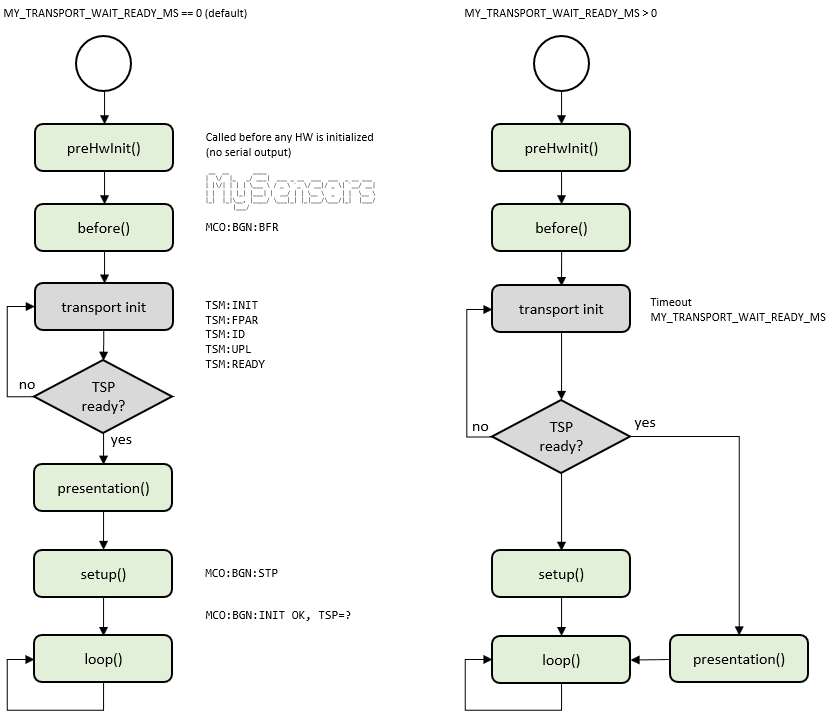
Received node id
When you enable auto id mode (default), the sensor automatically fetches a unique node id from the controller. The id received can be retrieved by calling this method.
uint8_t getNodeId();Presentation
The sensors should present themselves before they start reporting sensor data to the controller. Do these calls in your presentation()-function
bool present(uint8_t childSensorId, uint8_t sensorType, const char *description, bool echo);childSensorId - The unique child id you want to choose for the sensor connected to this Arduino. Range 0-254.
sensorType - The sensor type you want to create.
description An optional textual description of the attached sensor.
echo - Set this to true if you want destination node to echo the message back to this node. Default is not to request echo. If set to true, the final destination will echo back the contents of the message, triggering the receive() function on the original node with a copy of the message, with message.isEcho() set to true and sender/destination switched.
Returns true if message reached the first stop on its way to destination.
You can also send in some optional meta information for this sensor node.
bool sendSketchInfo(const char *name, const char *version, bool echo);name - String containing a short Sketch name or NULL if not applicable. Max 25 characters.
version - String containing a short Sketch version or NULL if not applicable.
echo - Set this to true if you want destination node to echo the message back to this node. Default is not to request echo. If set to true, the final destination will echo back the contents of the message, triggering the receive() function on the original node with a copy of the message, with message.isEcho() set to true and sender/destination switched.
Returns true if message reached the first stop on its way to destination.
Sending data
You can send data to the controller or some other sensor by using the send(msg) method.
bool send(MyMessage &msg, bool echo);msg - The message you want to send. See MyMessage for details.
echo - Set this to true if you want destination node to echo the message back to this node. Default is not to request echo. If set to true, the final destination will echo back the contents of the message, triggering the receive() function on the original node with a copy of the message, with message.isEcho() set to true and sender/destination switched.
Returns true if message reached the first stop on its way to destination.
If your node is running on batteries and you've implemented battery level measurements you can send the battery level back to the controller.
bool sendBatteryLevel(uint8_t level, bool echo);level - Battery level between 0-100(%)
echo - Set this to true if you want destination node to echo the message back to this node. Default is not to request echo. If set to true, the final destination will echo back the contents of the message, triggering the receive() function on the original node with a copy of the message, with message.isEcho() set to true and sender/destination switched.
Returns true if message reached the first stop on its way to destination.
Sending a heartbeat to the controller (I'm alive!).
bool sendHeartbeat();Returns true if message reached the first stop on its way to destination.
Handling incoming radio messages
Nodes that expects incoming data, such as an actuator or repeating nodes, must implement the receive()-function to handle the incoming messages. Do not sleep a node where you expect incoming data or you will lose messages.
void receive(const MyMessage &message)message - The incoming message data
Requesting data
Requests a variable value from gateway or some other sensor in the radio network. Make sure to add a receive()-function to handle request responses. If you send this request to some other sensor-node you must handle the reply message yourself in the destination node.
void request(uint8_t childSensorId, uint8_t variableType, uint8_t destination);childSensorId - The unique child id for the different sensors connected to this Arduino. 0-254.
variableType - The variableType to fetch.
destination - The nodeId of other node to request data from in radio network. Default is gateway.
Fetching time from controller
Requests time from controller. Answer will be delivered to your receiveTime()-function function in sketch.
bool requestTime();

bool receiveTime(uint32_t ts);
ts - Time in seconds since 1970. Adjusted for timezone by controller.
Returns true if message reached the first stop on its way to destination.
Controller configuration
Your sensor is responsible for reporting data in the correct units of measure. The controller can give you a "hint" for which units of measure to report. The following returns the most recent node configuration received from controller.
ControllerConfig getControllerConfig();ControllerConfig only contains the filed isMetric today which has the following meaning:
true (=metric) Report sensor data in Celsius, meter, cm, gram, km/h, m/s etc..
false (=imperial) - Fahrenheit, feet, gallon, mph etc...
Saving state
You can save a state (in local EEPROM) which is good for actuators to "remember" state between power cycles. You have 256 bytes to play with. Note that there is a limitation on the number of writes the EEPROM can handle (~100 000 cycles).
void saveState(uint8_t pos, uint8_t value);pos - The position to store value in (0-255)
value - Value to store in position
Retrieving a state (from local EEPROM).
uint8_t loadState(uint8_t pos);pos - The position to fetch from EEPROM (0-255)
Waiting
Waiting using the Arduino delay() command is not a good idea. It halts all MySensors processing and should be avoided. Instead you should use the provided wait function which calls process() while waiting, which handles incoming messages and repeater functions. Note that it doesn't power down the Arduino or radio while waiting. Use sleep if you want to save battery.
void wait(unsigned long ms);ms - The number of milliseconds to wait (while still processing incoming data)
Waits for a specific message to arrive (or for maximum time in milliseconds).
bool wait(unsigned long ms, uint8_t cmd, uint8_t msgtype);ms - The number of milliseconds to wait (while still processing incoming data)
cmd - The command type to wait for
msgtype - The message type to wait for
Sleeping
To save battery it is crucial to sleep you node as much as possible. The node can wake up from external interrupts or by a timer.
Each sleep function has a "smart" variant, which sends heartbeat and process incoming messages before going to sleep. This is useful for sending out firmwares or commands for sleeping nodes. The controller must support buffering of messages and send them when node wakes up.
The following sleep your radio and Arduino (in PowerDownMode). Wakes up on timer interrupt.
void sleep(unsigned long ms);
void smartSleep(unsigned long ms);
ms - Number of milliseconds to sleep.
The following sleeps your radio and Arduino (in PowerDownMode). Wakes up on timer interrupt or from an external interrupt.
See: http://arduino.cc/en/Reference/attachInterrupt for details on modes and which pin is assigned to what interrupt. On Nano/Pro Mini: 0=Pin2, 1=Pin3
int8_t sleep(int interrupt, int mode, unsigned long ms=0);
int8_t smartSleep(int interrupt, int mode, unsigned long ms=0);
interrupt - Interrupt that should trigger the wakeup.
mode - RISING, FALLING, CHANGE
ms - Number of milliseconds to sleep (or 0 to sleep forever).
Returns the interrupt number if wake up was triggered by pin change, MY_SLEEP_NOT_POSSIBLE if sleep was not possible and MY_WAKE_UP_BY_TIMER if timer woke it up.
int8_t sleep(uint8_t interrupt1, uint8_t mode1, uint8_t interrupt2, uint8_t mode2, unsigned long ms=0);
int8_t smartSleep(uint8_t interrupt1, uint8_t mode1, uint8_t interrupt2, uint8_t mode2, unsigned long ms=0);
interrupt1 - First interrupt that should trigger the wakeup.
mode1 - Mode for first interrupt (RISING, FALLING, CHANGE)
interrupt2 - Second interrupt that should trigger the wakeup.
mode2 - Mode for second interrupt (RISING, FALLING, CHANGE)
ms - Number of milliseconds to sleep (or 0 to sleep forever).
Returns the interrupt number if wake up was triggered by pin change, MY_SLEEP_NOT_POSSIBLE if sleep was not possible and MY_WAKE_UP_BY_TIMER if timer woke it up.
Note that when the node is sleeping, the millis timer will be frozen and the radio will be turned off.
Here is an example on how to do sleeping on timer and interrupt, contributed by @BearWithBeard:
#define MY_RADIO_RF24
#include <MySensors.h>

#define CHILD_ID 1
MyMessage msg(CHILD_ID, V_STATUS);

#define INT_PIN 3
#define LED_PIN 5
bool ledState = false;

#define SLEEP_TIME 9000000 // 15 min
uint32_t sleepTime = SLEEP_TIME;
int8_t wakeupReason = MY_WAKE_UP_BY_TIMER; // Initial value, will be set by sleep after the first run

void presentation()
{
    sendSketchInfo("Sleep + Interrupts", "1.0");
    present(CHILD_ID, S_BINARY);
}

void setup()
{
    pinMode(LED_PIN, OUTPUT);
    digitalWrite(LED_PIN, ledState);
}

void loop()
{
    if (wakeupReason == digitalPinToInterrupt(INT_PIN)) {
        sleepTime = getSleepRemaining();
        // Do interrupt-triggered stuff here
        // Sends the pin state when woken up by external interrupt
        send(msg.set(digitalRead(INT_PIN)));
    } else if (wakeupReason == MY_WAKE_UP_BY_TIMER) {
        sleepTime = SLEEP_TIME;
        // Do periodical stuff here
        // Toggles the LED every 15 minutes
        ledState = !ledState;
        digitalWrite(LED_PIN, ledState);
    }
    wakeupReason = sleep(digitalPinToInterrupt(INT_PIN), CHANGE, sleepTime);
}
Message Signing
For enabling signed messages, there is an excellent guide here.
Message constructor
Create an instance of MyMessage. This class holds the message data and have some helpers for setting payload.
MyMessage(uint8_t childSensorId, uint8_t variableType);childSensorId - The child sensor id to report data on. 0-254.
variableType - Variable type.
Message manipulation
You can manipulate your outgoing and incoming messages with the following getter/setters.
    // Setters for building message "on the fly"
    MyMessage& setType(uint8_t type);
    MyMessage& setSensor(uint8_t sensor);
    MyMessage& setDestination(uint8_t destination);

    // Setters for payload
    MyMessage& set(void* payload, uint8_t length);
    MyMessage& set(const char* value);
    MyMessage& set(uint8_t value);
    MyMessage& set(float value, uint8_t decimals);
    MyMessage& set(unsigned long value);
    MyMessage& set(long value);
    MyMessage& set(unsigned int value);
    MyMessage& set(int value);

    // Getter for echo-flag. Returns true if this is an echoed message.
    bool isEcho() const;

    // Getters for picking up payload on incoming messages
    char* getStream(char *buffer) const;
    char* getString(char *buffer) const;
    const char* getString() const;
    void* getCustom() const;
    uint8_t getByte() const;
    bool getBool() const;
    float getFloat() const;
    long getLong() const;
    unsigned long getULong() const;
    int getInt() const;
    unsigned int getUInt() const;