Firmware over the air, FOTA, lets you upload your firmware (the sketch) wirelessly. It can be useful if your nodes are not accessible and you want to update your firmware, or change some hardwritten config.
FOTA can be implemented in different ways if using an Esp8266 mcu, 8bits 328p (like Arduino Pro mini etc) or an ARM.
- For the moment, this tutorial covers 328p only.
- For Esp8266, you can get details how to handle FOTA in your sketch here : http://esp8266.github.io/Arduino/versions/2.1.0-rc2/doc/ota_updates/ota_updates.html
- For ARM boards like Arduino Zero, it is not available yet.
Let's show you how to get started with this nice feature.
The FOTA bootloader
Before using FOTA, you will need to burn the right bootloader.
Noobs note : shortly, a bootloader is a piece of code which is executed at reset/startup, and let you upload your firmware by usb or other methods, instead of using AVRSPI.
In Mysensors, we can use two kind of FOTA:
- 1st option : MYSBootloader, created by Tekka from Mysensors Team.
- 2nd option : Dualoptiboot which comes from Lowpowerlab and is the bootloader used in the Sensebender Micro.
MYSBootloader does not require external flash. FOTA updates are transmitted offline, i.e. MYSBootloader communicates with the controller and receives new FW which is directly written to MCU, once FW is transmitted and CRC verified, MYSBootloader hands over to the new sketch/FW.
MYSBootloader uses channel 76 by default. To change the channel, a new bootloader must be compiled.
- Pro: recovery FOTA possible, also with a faulty/buggy sketch (if sketch freezes, watchdog resets and MYSBootloader takes over), no external flash required
- Cons: Radio specific, i.e. different bootloader for RF24 and RFM69 radio (rfm69 work in progess) necessary, offline (no sensor data processing possible during fota). The MySensors master branch does not support upload through ftdi / serial (but the development branch does).
Dualoptiboot requires external flash: FOTA updates are transmitted online, i.e. while the node is active. Once all FW packets are transmitted and CRC verified, the node reboots, dualoptiboot copies FW from external flash to MCU and hands over to the new sketch/FW. That means too that you need to ftdi upload your node sketch the first time or fota won't work yet as it is handled in the sketch.
- Pro: Radio agnostic (no radio specific code in bootloader so can be used in different scheme/protocols..), online (while node processes sensor data)
- Cons: Faulty FW (e.g. freezing sketch due to bad coding) cannot be recovered FOTA => recovery via serial port necessary, external flash required
What do you need
More generally, you will need this :
- An USBASP to burn the bootloader (or you can also use ArduinoAsIsp, not covered here)
- Install AVRDUDESS : http://blog.zakkemble.co.uk/avrdudess-a-gui-for-avrdude/ for fuses configuration
- Arduino IDE 1.6.x installed
- Mysensors lib > 1.5.x installed : https://www.mysensors.org/about/arduino
- MYSController : https://www.mysensors.org/controller/myscontroller
If you want to use the DualOptiboot bootloader, you will need :
- SPI flash, jedec compliant, like AT25DF512C-SSHN-B. For other flash chips and compatibility, you can check this post https://forum.mysensors.org/topic/3160/ota-flash-types-for-mysensors
- for evaluation or some diy projects there is also https://oshpark.com/shared_projects/m5Uugjx5 or https://www.openhardware.io/view/18/OTA-and-Authentication-Evaluation-Board. If you have a Sensebender Micro or a Moteino, you already have the spi flash ic onboard.
Now you should see Sensebender Micro board in Boards\tools of Arduino Ide.
Burning the bootloader
Here we are using an Usbasp for programming the bootloader. It is easy to use and cheap tool. Connect your Usbasp programmer device to your "Arduino" device.
What looks usbasp (clone, USBASP 2.0 LC Technology) and connections to your arduino or node
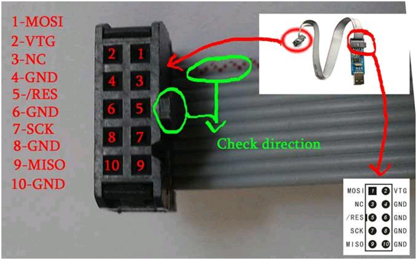
| Connector | Arduino Nano/Micro/328p/Sensebender etc |
|---|---|
| MOSI | D11 |
| VTG | VCC 3.3V |
| GND | GND |
| RES | RESET |
| SCK | D13 |
| MISO | D12 |
Here is a video describing the bootloader burning process.
Once it's wired, burn fuses with Avrdudess. Here is the configuration for an Internal Oscillator 8Mhz device:
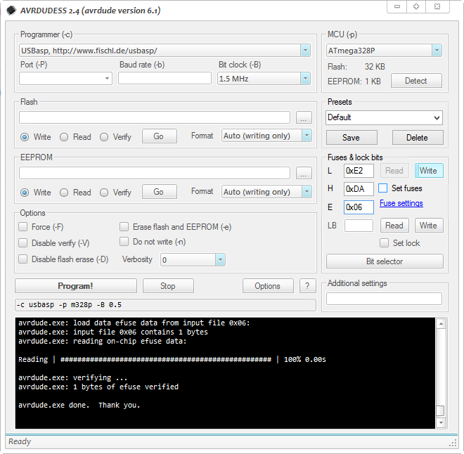
Here is for an External Oscillator 16Mhz device:
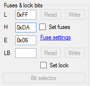
Note : even if using an Usbasp clone, choose genuine Usbasp in the listbox.
- Click on Write in "Fuses&Lock bits" section. Then read it to check fuses are well burnt. Now don't disconnect your Usbasp.
- Go to Arduino Ide, in Board Manager, choose SensebenderMicro if you want to use DualOptiboot bootloader FOTA. Or choose Arduino Mini pro MYSBootloader
- Then choose Processeur Atmel328 8Mhz, USBASP As programmer.
- Click Tools\Burn bootloader. You will get few SCK warning but that's not a problem, it's because this is an Usbasp clone.
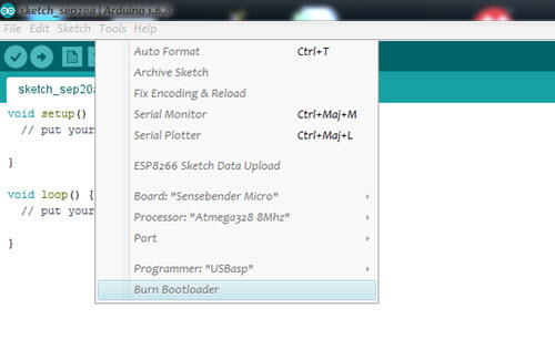
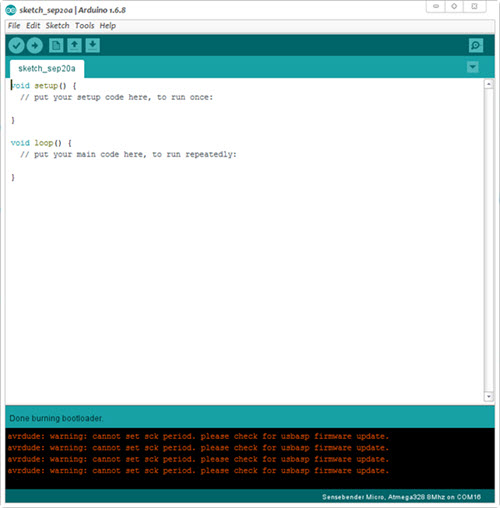
Yeah, our FOTA bootloader is burnt.
If you get an error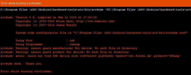
Some versions of the Arduino IDE don't see the USBasp. If you get an error message that looks similar to the screenshot above, the fix is posted here: http://forum.arduino.cc/index.php?topic=415210.msg2862244#msg2862244
Notes:
- you can also use Avrdudess for burning the bootloader.
- DualOptiboot : 8Mhz Internal + 1.8V BOD.
Enabling FOTA in your sketch (DualOptiboot only)
To enable FOTA in your sketch, you need to add
#define MY_OTA_FIRMWARE_FEATURE FOTA management is completely transparent. Everything is well handled by Mysensors lib in process() and wait()
But it is Important to note :
- Don't forget a sleeping node can't receive an FOTA. You can wait after wakeup for instance to see if you have somethings coming or there is smartsleep() which manage the wait() after wake up.
In case of Dualoptiboot (does not concern MYSBootloader as it is offline FOTA):
- When you upload the new sketch, it is done during runtime, so you have to handle/optimize this in sketch. The best is if you detect an FOTA msg, to pause process or sensors readings during the process or it will affect the speed of the FOTA. For instance if you read sensors, sometimes there are some delays in libs, all these things will delay FOTA or timeout it during main loop. Plus, if these optimization are not done and you run on battery, the longer time in TX/RX radio for the update, the more battery energy wasted.
- FOTA can be fast 15-30sec if nothing slow it, or x minutes if not optimized. So it's up to you to manage this, using non blocking/asynchronous code is always a good idea. The rest of the process is completely transparent. Great!
How to upload a new sketch just with FOTA
You will need to use .hex file instead of .ino .
To easily get this file : in Arduino ide, go to File\Preferences, on bottom click on preferences.txt. It opens preferences.txt.
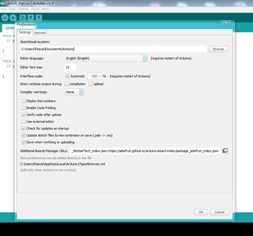 2. Keep this file opened and close Arduino ide (otherwise your changes will be erased).
- In preferences.txt, at the end, add this
or another preferred path. That will be the output folder for your .hex compiled sketch files. Close the dialog box.build.path=C:\Arduino-Output\
- Open Arduino ide and compile/check your node project. You should now see your compiled files in the folder you have set previously.
- Copy the .hex to Firmware path of MYSController if you use it.
Launch your FOTA update
- Open MYSController, go to Config/Serial, check the right Serial Com port for your GW.
- Click on "Refresh FW repo" so you can use your new .hex file.
Note : if you can't see your .hex, you can also do this : In Firmware folder, edit firmware_config.csv and manually add your .hex. Here an example where I added a Humidity .hex file for tests.
Type,Name,Version,File,Comments
10,Blink,1,Blink.hex,blinking example
20,TimeReporter,1,TimeReporter.hex,TimeReporter
100,Sensebender Micro,1,SensebenderMicro.cpp.hex,Sensebender Micro
110,Sensebender Blink,1,SensebenderBlink.cpp.hex,Sensebender Blink
120,Sensebender HumidityTest,1,HumiditySensor.cpp.hex,HumidityTest- Now to wirelessly send your new sketch to your node, simply right click on the node you want to update. For sleeping battery node, choose "Battery powered Sleeping". So when your node will wake up, MYSController will resend the update. Awesome!
- Click on Assign FW,
- Choose your .hex sketch
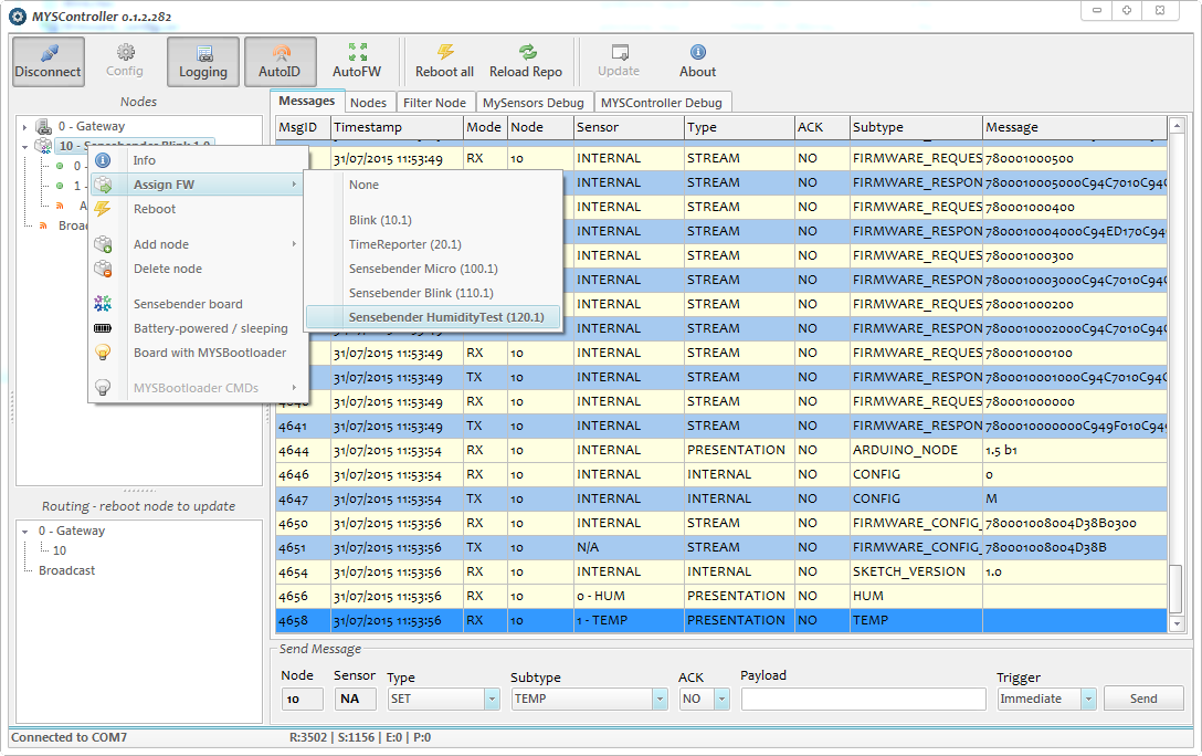
Voilà! FOTA should start, then your node will reboot and launch the new firmware.