The Radio Communication
In this section, you will learn the difference between Sensor, Repeater-sensor and Gateway.
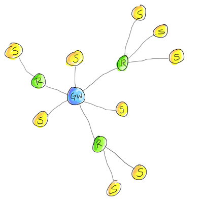
Your sensors will form a tree network topology. Normally the sensor nodes (S) will send their information directly to the gateway (GW). If you live in a mansion or very large house, you may need to enable the repeater mode for some sensor nodes (R) to relay data from sensors that are located far away from the gateway.
Sensor nodes - continuously read the status of all attached sensors and pass the sensor data through the radio network back to the gateway. These puppies have the option to sleep most of the time if you want to run them on battery.
Repeater-sensor nodes - must stay awake in order to pass messages from its child sensor nodes. A repeater-node can optionally include direct-attached sensors and report their sensor data to the gateway. In most setups you will probably not need any repeater-nodes as the transmitter range for the most basic radio is about 20-60 meters.
Gateway - passes data from nodes to your home automation controller as well as from the home automation controller back to nodes. You can attach sensors directly to the gateway as well.
Skip the following section if you aren't inspired by technical details
You can also send messages directly between two nodes in the network without transiting through the gateway. For example, your outside temperature sensor can send its data directly to another sensor in your kitchen with an attached display.
Each node is assigned a unique sensorId or address that is used for sending and receiving point-to-point messages. You can assign a static sensorId (in the sketch) or let the controller automatically assign one to the sensor. AUTO-mode configures the sensor to request a sensorId from the controller and is the default option for all the examples that we provide. The sensor stores the assigned sensorId in its non-volatile memory to ensure the correct sensorId persists across power transitions. A gateway always has sensorId 0.
The first time a new sensor boots up, it will determine the path to the gateway by sending out a special Help-me-find-my-way-home-message. The repeater-sensor nodes and gateway listen for these messages and will respond to a sensor's plea-for-help-message. Their reply will inform the sensor how far they are from the gateway so the newly born sensor can determine the shortest path to the gateway, be it directly to the gateway or through a repeater-sensor node which is the closest to the gateway. If the sensor node later loses contact with the gateway or a repeater-sensor node, it will automatically repeat this procedure to determine the best path to the gateway - a sensor node considers contact with the gateway to be lost if it fails to send 3 consecutive messages.
Gateway and repeater-sensor nodes maintain a small routing table to know where to direct their messages to the network surrounding it. The routing table is built up automatically by the repeaters and gateway by introspecting messages received.
A MySensor radio network can consist of up to 254 different radio nodes and each radio node can report data for 254 attached child sensors. This means that you can, in theory, manage data for up to 64516 sensors in a single radio network. If this isn't enough, you can create another parallel radio network on a different channel and there are 126 available channels [NRF24L01+].
To summarize: New nodes will automatically find the shortest path to gateway and and use a persistent unique sensorId to send and receive point-to-point messages. The tree network is robust and "self heals" as the topology changes. For example, you move a sensor node to a different physical location or a repeater-node dies.
The Controller
The radio gateway is typically connected to some kind of controller. The purpose of the controller is:
- Send configuration parameters to the sensors in the radio network (currently time, and unique sensor ids)
- Keep track of the most recent data reported by sensors and actuators.
- Provide status information back to sensors and actuators; e.g. the current state (on/off/loadLevel) for a light.
- The controller usually provides a user interface controls for actuators.
- Executes predefined schedules or scenes; e.g. at sunset turn on the garden lights.
MySensors currently offers support for for more than 20 different controllers.
Read more about selecting gateway and controller.