
 The MySensors Sensebender Micro is a tiny Arduino compatible board stackable with a Nordic NRF24L01+ transceiver module. The Micro has been designed for extended battery life; e.g. it operates directly at the battery voltage without the need for power regulators for low power consumption. As it has been designed to sleep most of the time, the operating frequency (8Mhz vs 1Mhz) is not that big a factor on battery consumption, hence the Micro is running at 8Mhz as default to facilitate the easiest adoption of sketches.
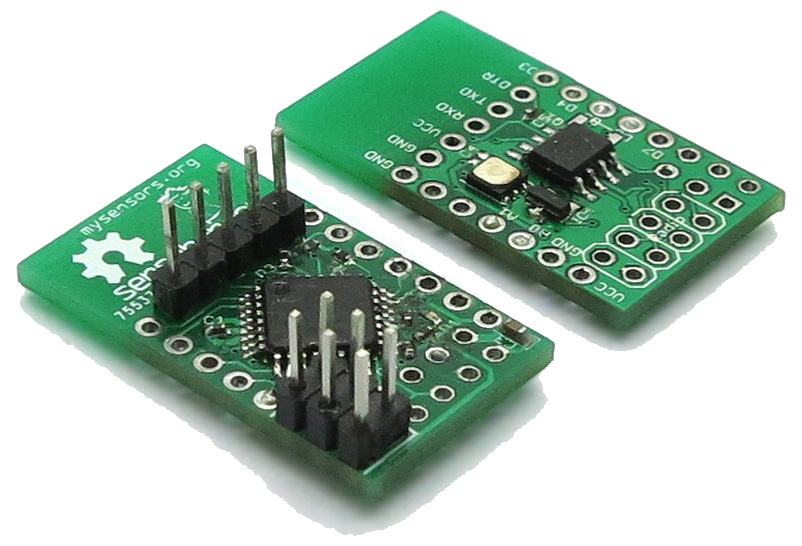 Even in its small form factor it's packed with great features such as temperature and humidity sensor, 64k extra flash memory and a hardware module for secure message signing and verification.
Need more? Expand the functionality by attaching additional breakout sensors to the five digital GPIOs, two analog inputs or the I2C interface.
The board has been preloaded with a sketch reporting temperature and humidity levels every minute.
Technical Specification
- Very small footprint, 30 mm x 17.5 mm (1.18in x 0.69 in). Making it almost same size as the NRF24 module.
- Arduino IDE 1.5.x & 1.6.x compatible.
- Si7021 integrated humidity / temperature sensor.
- 64kb SPI flash / e2prom onboard. Useful for over-the-air firmware updates. Also possible to use memory for a local sensor data cache.
- ATSHA204A on board (connected to A3). Used for HMAC-SHA256 message authentication support.
- Runs directly off 2x1.5V batteries (AA or AAA), without power converters.
- Socket* for connecting the radio module on top.
- Pin-headers* for D3-D7 on one side, and SDA/SCL + A0/A1 and power on the other side.
- FTDI header similar to Arduino Pro Mini.
- Standard Atmel programming ISCP header.
- Pads for mounting a 32Khz crystal (when timing is crucial).
- Status LED (on A2).
- Factory programmed with DualOptiBoot bootloader.
*) You have to solder the radio socket, and pin-headers yourself if you need them mounted. Note: The actual NRF24L01+ module is sold separately.
Available pins
- Powersupply (1.8 -> 3.5V)
- SDA / SCL (I2C bus)
- A0 / A1
- D3 / D4 / D5 / D6 / D7
- 6 pin ISP port
- 8 pin standard NRF24L01+ connector layout
- FTDI header for serial
Wiring Things Up
NOTE! Maximum allowed supply voltage is 3.5V, anything above this WILL fry both Si7021, flash and NRF24 radio module. There is NO voltage regulator on board (To keep supply current down to a minimum)
Available Pins
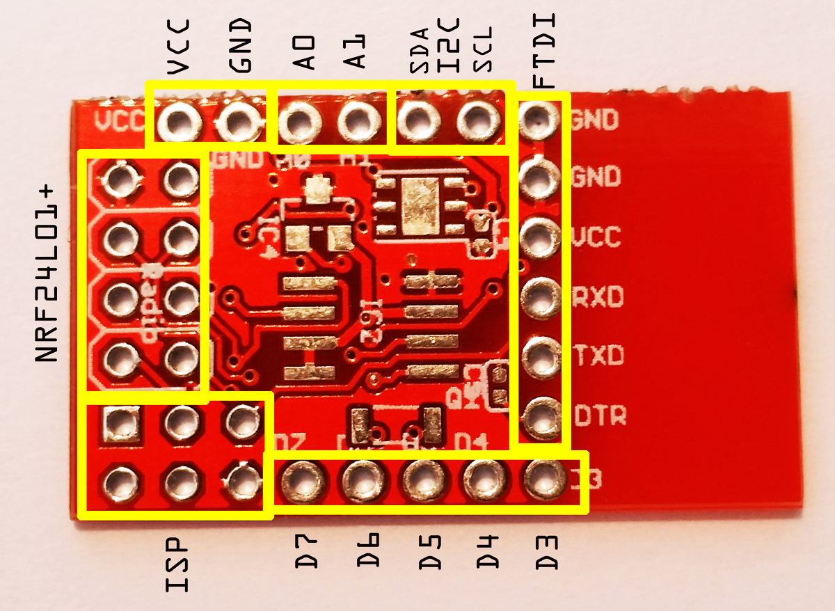
This picture shows all the available pins on the Micro board. Click on the image to enlarge it. The ISP connector exposes MISO, MOSI, SCK and RST.
Connecting Battery
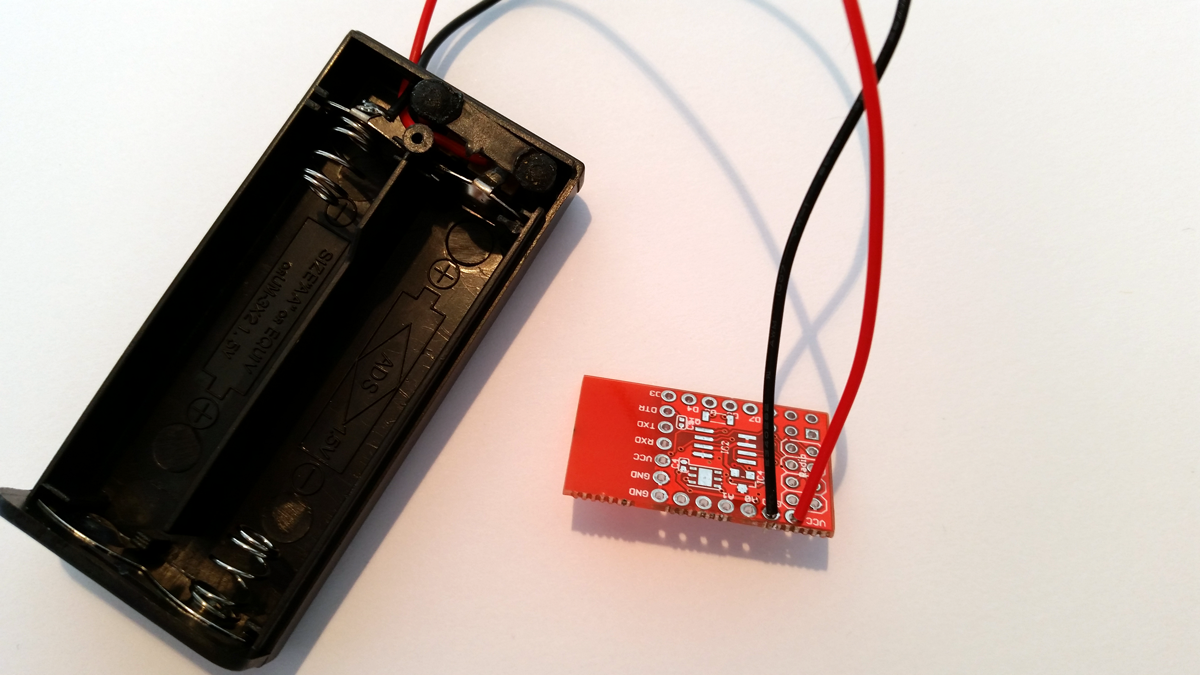
The board has been designed to operate at maximum 3V (2x1.5V batteries). Make sure not to overfeed it or reverse the polarity. This would permanently kill it. Connect:
GND to minus (-) often marked with a black wire.
VCC to plus (+) often marked with a red wire.
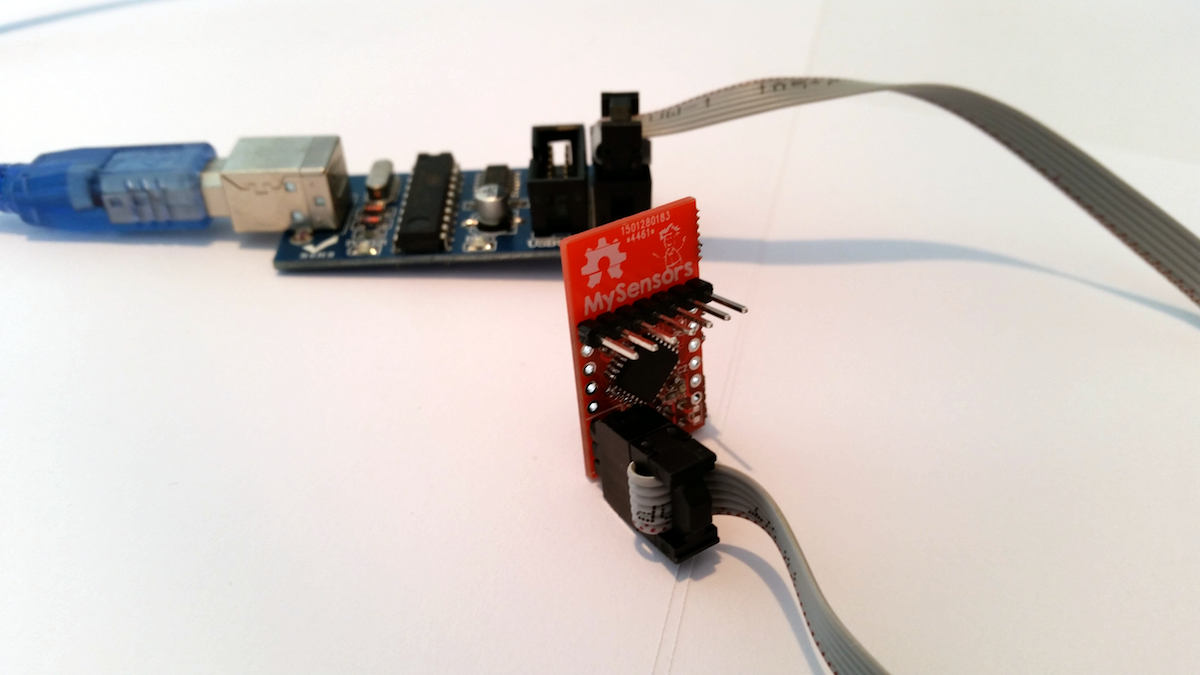
Connecting FTDI Programmer
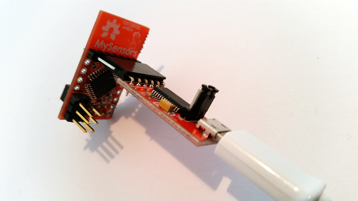
To upload a new sketch to your Micro board use a FTDI programmer. Remember to set it a 3v3 output using the jumper setting on the programmer.
Setting up Arduino IDE for SensebenderConnecting ISP Programmer
Make sure the red-dotted ISP wire goes into ground on the board. Disable power feeding on 5V ISP programmers (remove jumper) and power up the board on VCC/GND from a 3V power source.
Mounting Radio
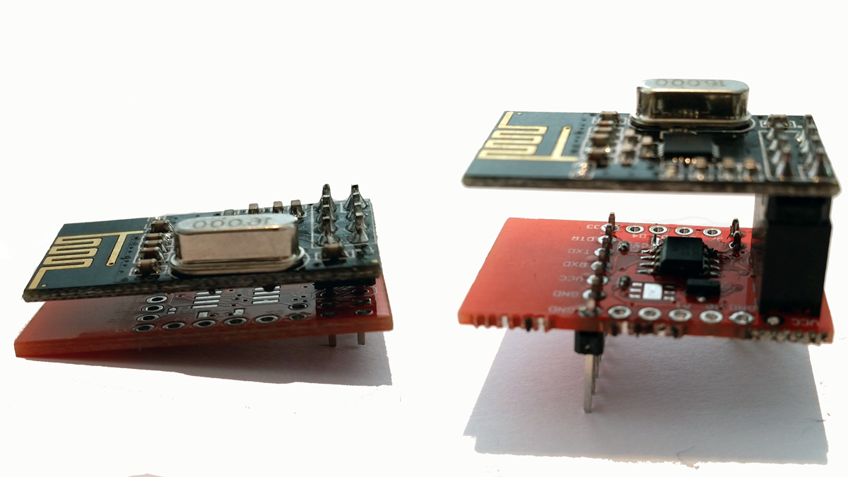
The radio can be soldered directly onto the board or in a socket.
Example Sketch
This example reports humidity and temperature levels to the controller every minute. To save battery it sleeps MCU and radio between sends.
If you connect A0 -> GND during power-up it will go into a self-test mode (reports status on serial output).

/**
 * The MySensors Arduino library handles the wireless radio link and protocol
 * between your home built sensors/actuators and HA controller of choice.
 * The sensors forms a self healing radio network with optional repeaters. Each
 * repeater and gateway builds a routing tables in EEPROM which keeps track of the
 * network topology allowing messages to be routed to nodes.
 *
 * Created by Henrik Ekblad <[email protected]>
 * Copyright (C) 2013-2015 Sensnology AB
 * Full contributor list: https://github.com/mysensors/Arduino/graphs/contributors
 *
 * Documentation: http://www.mysensors.org
 * Support Forum: http://forum.mysensors.org
 *
 * This program is free software; you can redistribute it and/or
 * modify it under the terms of the GNU General Public License
 * version 2 as published by the Free Software Foundation.
 *
 *******************************
 *
 * REVISION HISTORY
 * Version 1.0 - Thomas Bowman MC8rch
 *
 * DESCRIPTION
 * Default sensor sketch for Sensebender Micro module
 * Act as a temperature / humidity sensor by default.
 *
 * If A0 is held low while powering on, it will enter testmode, which verifies all on-board peripherals
 *
 * Battery voltage is as battery percentage (Internal message), and optionally as a sensor value (See defines below)
 *
 *
 * Version 1.3 - Thomas Bowman MC8rch
 * Improved transmission logic, eliminating spurious transmissions (when temperatuere / humidity fluctuates 1 up and down between measurements)
 * Added OTA boot mode, need to hold A1 low while applying power. (uses slightly more power as it's waiting for bootloader messages)
 *
 * Version 1.4 - Thomas Bowman MC8rch
 *
 * Corrected division in the code deciding whether to transmit or not, that resulted in generating an integer. Now it's generating floats as expected.
 * Simplified detection for OTA bootloader, now detecting if MY_OTA_FIRMWARE_FEATURE is defined. If this is defined sensebender automaticly waits 300mS after each transmission
 * Moved Battery status messages, so they are transmitted together with normal sensor updates (but only every 60th minute)
 *
 */

// Enable debug prints to serial monitor
//#define MY_DEBUG

// Define a static node address, remove if you want auto address assignment
//#define MY_NODE_ID 3

// Enable and select radio type attached
#define MY_RADIO_NRF24
//#define MY_RADIO_RFM69

// Enable to support OTA for this node (needs DualOptiBoot boot-loader to fully work)
#define MY_OTA_FIRMWARE_FEATURE

#include <SPI.h>
#include <MySensors.h>
#include <Wire.h>
#include <SI7021.h>
#ifndef MY_OTA_FIRMWARE_FEATURE
#include "drivers/SPIFlash/SPIFlash.cpp"
#endif
#include <EEPROM.h>
#include <sha204_lib_return_codes.h>
#include <sha204_library.h>
#include <RunningAverage.h>
//#include <avr/power.h>

// Uncomment the line below, to transmit battery voltage as a normal sensor value
//#define BATT_SENSOR    199

#define RELEASE "1.4"

#define AVERAGES 2

// Child sensor ID's
#define CHILD_ID_TEMP  1
#define CHILD_ID_HUM   2

// How many milli seconds between each measurement
#define MEASURE_INTERVAL 60000

// How many milli seconds should we wait for OTA?
#define OTA_WAIT_PERIOD 300

// FORCE_TRANSMIT_INTERVAL, this number of times of wakeup, the sensor is forced to report all values to the controller
#define FORCE_TRANSMIT_INTERVAL 30

// When MEASURE_INTERVAL is 60000 and FORCE_TRANSMIT_INTERVAL is 30, we force a transmission every 30 minutes.
// Between the forced transmissions a tranmission will only occur if the measured value differs from the previous measurement

// HUMI_TRANSMIT_THRESHOLD tells how much the humidity should have changed since last time it was transmitted. Likewise with
// TEMP_TRANSMIT_THRESHOLD for temperature threshold.
#define HUMI_TRANSMIT_THRESHOLD 0.5
#define TEMP_TRANSMIT_THRESHOLD 0.5

// Pin definitions
#define TEST_PIN       A0
#define LED_PIN        A2
#define ATSHA204_PIN   17 // A3

const int sha204Pin = ATSHA204_PIN;
atsha204Class sha204(sha204Pin);

SI7021 humiditySensor;
SPIFlash flash(8, 0x1F65);

// Sensor messages
MyMessage msgHum(CHILD_ID_HUM, V_HUM);
MyMessage msgTemp(CHILD_ID_TEMP, V_TEMP);

#ifdef BATT_SENSOR
MyMessage msgBatt(BATT_SENSOR, V_VOLTAGE);
#endif

// Global settings
int measureCount = 0;
int sendBattery = 0;
boolean isMetric = true;
boolean highfreq = true;
boolean transmission_occured = false;

// Storage of old measurements
float lastTemperature = -100;
int lastHumidity = -100;
long lastBattery = -100;

RunningAverage raHum(AVERAGES);

/****************************************************
 *
 * Setup code
 *
 ****************************************************/
void setup() {

  pinMode(LED_PIN, OUTPUT);
  digitalWrite(LED_PIN, LOW);

  Serial.begin(115200);
  Serial.print(F("Sensebender Micro FW "));
  Serial.print(RELEASE);
  Serial.flush();

  // First check if we should boot into test mode

  pinMode(TEST_PIN,INPUT);
  digitalWrite(TEST_PIN, HIGH); // Enable pullup
  if (!digitalRead(TEST_PIN)) testMode();

  // Make sure that ATSHA204 is not floating
  pinMode(ATSHA204_PIN, INPUT);
  digitalWrite(ATSHA204_PIN, HIGH);

  digitalWrite(TEST_PIN,LOW);

  digitalWrite(LED_PIN, HIGH);

  humiditySensor.begin();

  digitalWrite(LED_PIN, LOW);

  Serial.flush();
  Serial.println(F(" - Online!"));

  isMetric = getControllerConfig().isMetric;
  Serial.print(F("isMetric: ")); Serial.println(isMetric);
  raHum.clear();
  sendTempHumidityMeasurements(false);
  sendBattLevel(false);

#ifdef MY_OTA_FIRMWARE_FEATURE
  Serial.println("OTA FW update enabled");
#endif

}

void presentation()  {
  sendSketchInfo("Sensebender Micro", RELEASE);

  present(CHILD_ID_TEMP,S_TEMP);
  present(CHILD_ID_HUM,S_HUM);

#ifdef BATT_SENSOR
  present(BATT_SENSOR, S_POWER);
#endif
}


/***********************************************
 *
 *  Main loop function
 *
 ***********************************************/
void loop() {

  measureCount ++;
  sendBattery ++;
  bool forceTransmit = false;
  transmission_occured = false;

  if (measureCount >= FORCE_TRANSMIT_INTERVAL) { // force a transmission
    forceTransmit = true;
    measureCount = 0;
  }

  sendTempHumidityMeasurements(forceTransmit);
/*  if (sendBattery > 60)
  {
     sendBattLevel(forceTransmit); // Not needed to send battery info that often
     sendBattery = 0;
  }*/
#ifdef MY_OTA_FIRMWARE_FEATURE
  if (transmission_occured) {
      wait(OTA_WAIT_PERIOD);
  }
#endif

  sleep(MEASURE_INTERVAL);
}


/*********************************************
 *
 * Sends temperature and humidity from Si7021 sensor
 *
 * Parameters
 * - force : Forces transmission of a value (even if it's the same as previous measurement)
 *
 *********************************************/
void sendTempHumidityMeasurements(bool force)
{
  bool tx = force;

  si7021_env data = humiditySensor.getHumidityAndTemperature();

  raHum.addValue(data.humidityPercent);

  float diffTemp = abs(lastTemperature - (isMetric ? data.celsiusHundredths : data.fahrenheitHundredths)/100.0);
  float diffHum = abs(lastHumidity - raHum.getAverage());

  Serial.print(F("TempDiff :"));Serial.println(diffTemp);
  Serial.print(F("HumDiff  :"));Serial.println(diffHum);

  if (isnan(diffHum)) tx = true;
  if (diffTemp >= TEMP_TRANSMIT_THRESHOLD) tx = true;
  if (diffHum >= HUMI_TRANSMIT_THRESHOLD) tx = true;

  if (tx) {
    measureCount = 0;
    float temperature = (isMetric ? data.celsiusHundredths : data.fahrenheitHundredths) / 100.0;

    int humidity = data.humidityPercent;
    Serial.print("T: ");Serial.println(temperature);
    Serial.print("H: ");Serial.println(humidity);

    send(msgTemp.set(temperature,1));
    send(msgHum.set(humidity));
    lastTemperature = temperature;
    lastHumidity = humidity;
    transmission_occured = true;
    if (sendBattery > 60) {
     sendBattLevel(true); // Not needed to send battery info that often
     sendBattery = 0;
    }
  }
}

/********************************************
 *
 * Sends battery information (battery percentage)
 *
 * Parameters
 * - force : Forces transmission of a value
 *
 *******************************************/
void sendBattLevel(bool force)
{
  if (force) lastBattery = -1;
  long vcc = readVcc();
  if (vcc != lastBattery) {
    lastBattery = vcc;

#ifdef BATT_SENSOR
    float send_voltage = float(vcc)/1000.0f;
    send(msgBatt.set(send_voltage,3));
#endif

    // Calculate percentage

    vcc = vcc - 1900; // subtract 1.9V from vcc, as this is the lowest voltage we will operate at

    long percent = vcc / 14.0;
    sendBatteryLevel(percent);
    transmission_occured = true;
  }
}

/*******************************************
 *
 * Internal battery ADC measuring
 *
 *******************************************/
long readVcc() {
  // Read 1.1V reference against AVcc
  // set the reference to Vcc and the measurement to the internal 1.1V reference
  #if defined(__AVR_ATmega32U4__) || defined(__AVR_ATmega1280__) || defined(__AVR_ATmega2560__)
    ADMUX = _BV(REFS0) | _BV(MUX4) | _BV(MUX3) | _BV(MUX2) | _BV(MUX1);
  #elif defined (__AVR_ATtiny24__) || defined(__AVR_ATtiny44__) || defined(__AVR_ATtiny84__)
    ADMUX = _BV(MUX5) | _BV(MUX0);
  #elif defined (__AVR_ATtiny25__) || defined(__AVR_ATtiny45__) || defined(__AVR_ATtiny85__)
    ADcdMUX = _BV(MUX3) | _BV(MUX2);
  #else
    ADMUX = _BV(REFS0) | _BV(MUX3) | _BV(MUX2) | _BV(MUX1);
  #endif

  delay(2); // Wait for Vref to settle
  ADCSRA |= _BV(ADSC); // Start conversion
  while (bit_is_set(ADCSRA,ADSC)); // measuring

  uint8_t low  = ADCL; // must read ADCL first - it then locks ADCH
  uint8_t high = ADCH; // unlocks both

  long result = (high<<8) | low;

  result = 1125300L / result; // Calculate Vcc (in mV); 1125300 = 1.1*1023*1000
  return result; // Vcc in millivolts

}

/****************************************************
 *
 * Verify all peripherals, and signal via the LED if any problems.
 *
 ****************************************************/
void testMode()
{
  uint8_t rx_buffer[SHA204_RSP_SIZE_MAX];
  uint8_t ret_code;
  byte tests = 0;

  digitalWrite(LED_PIN, HIGH); // Turn on LED.
  Serial.println(F(" - TestMode"));
  Serial.println(F("Testing peripherals!"));
  Serial.flush();
  Serial.print(F("-> SI7021 : "));
  Serial.flush();

  if (humiditySensor.begin())
  {
    Serial.println(F("ok!"));
    tests ++;
  }
  else
  {
    Serial.println(F("failed!"));
  }
  Serial.flush();

  Serial.print(F("-> Flash : "));
  Serial.flush();
  if (flash.initialize())
  {
    Serial.println(F("ok!"));
    tests ++;
  }
  else
  {
    Serial.println(F("failed!"));
  }
  Serial.flush();


  Serial.print(F("-> SHA204 : "));
  ret_code = sha204.sha204c_wakeup(rx_buffer);
  Serial.flush();
  if (ret_code != SHA204_SUCCESS)
  {
    Serial.print(F("Failed to wake device. Response: ")); Serial.println(ret_code, HEX);
  }
  Serial.flush();
  if (ret_code == SHA204_SUCCESS)
  {
    ret_code = sha204.getSerialNumber(rx_buffer);
    if (ret_code != SHA204_SUCCESS)
    {
      Serial.print(F("Failed to obtain device serial number. Response: ")); Serial.println(ret_code, HEX);
    }
    else
    {
      Serial.print(F("Ok (serial : "));
      for (int i=0; i<9; i++)
      {
        if (rx_buffer[i] < 0x10)
        {
          Serial.print('0'); // Because Serial.print does not 0-pad HEX
        }
        Serial.print(rx_buffer[i], HEX);
      }
      Serial.println(")");
      tests ++;
    }

  }
  Serial.flush();

  Serial.println(F("Test finished"));

  if (tests == 3)
  {
    Serial.println(F("Selftest ok!"));
    while (1) // Blink OK pattern!
    {
      digitalWrite(LED_PIN, HIGH);
      delay(200);
      digitalWrite(LED_PIN, LOW);
      delay(200);
    }
  }
  else
  {
    Serial.println(F("----> Selftest failed!"));
    while (1) // Blink FAILED pattern! Rappidly blinking..
    {
    }
  }
}