
 The MySensors Sensebender Gateway is a compact Arduino Zero compatible board that is purpose-built by the MySensors team to serve as a fully-functional, high-performance MySensors gateway.
The MySensors gateway is the first device you will need for your MySensors network and this one is designed from the ground up for both novices and experts. The gateway supports the nRF24L01+ or RFM69 radios and can interface with a wide array of HA controllers via USB or Ethernet.
If you want to get up and running quickly with a no-compromise and flexible gateway designed and supported by the MySensors Team, then this is the gateway for you.
Features
High Performance MCU
At it’s core, the Gateway is equipped with a high-performance Atmel SAMD21 MCU running at 48MHz offering plenty of headroom for advanced gateway-specific features as the MySensors ecosystem expands. The SAMD21 MCU product line is Atmel’s ARM Cortex offering equipped with 32Kb of RAM and 256Kb for flash providing ample working and persistent storage for current and future gateway tasks.
Broad Home Automation Controller Support
The Gateway is compatible with more than 20 of the most common home automation controllers on the market using either USB or Ethernet. Literally all requested automation controllers are currently supported and the list continues to expand… Don’t see yours, it is easy to write an adapter and we are here to help you.
Secure IoT Radio Network
The Gateway includes footprints/pads for two very common radios supported by MySensors; the Nordic nRF24L01+ radio or the Hope RF RFM69HW radio offering users different options for their locale/home construction and IoT projects. Each Gateway includes an ATSHA204 CryptoAuthentication chip that can be used for hardware-based message signing for secure radio communications, after personalisation.
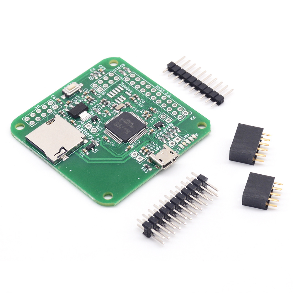
Expandability The Gateway also includes an MYSX 2.6 connector that breaks out plenty of IO pins for DIY shields that can be used to add sensors and actuators to the gateway or to use the gateway board as a compact, high-performance node for more demanding IoT projects and applications. In addition, the Gateway includes a micro-sd card reader for IoT applications where additional local non-volatile storage is required (e.g. configuration files, storing time-series sensor readings for offline analysis, etc.).
Technical Specifications
- Board size 5x5cm
- Atmel ATSAMD21 (Arm cortex m0+ cpu core) with
- 256Kb flash
- 32Kb RAM
- 48Mhz clock
- RTC module
- Micro sd card reader
- Socket for nRF24L01+ module (module not included)
- Pads for RFM69 module (module not included)
- Socket for W5100 ethernet module (module not included)
- Native USB port
- ATSHA204A for signing
- Onboard i2c eeprom
- 5 LED's (Red, Green, Yellow, Blue and Orange)
- MYSx 2.6 with
- Dedicated UART
- Dedicated SPI
- Dedicated Interrupts
- I2C bus (shared with onboard eeprom)
Setup and use
You need to add your own radio, either NRF24L01+ or RFM69(H)W radio modules, which you can find in our shop under the radio section, Also if you want to use it as an ethernet gateway, you need to purchase a W5100 ethernet module, the small breakout edition is the one to choose.
Windows drivers
You will need to install the SenseBender GW driver if you are running a version of Windows older than Windows 10. See Appendix A below for driver install instructions.
Default sketch
The factory default sketch is a serial gateway using NRF24L01 radio and no signing. If you want to use it in this configuration, then it's just adding the box header for the NRF24L01 module, plug the radio in, and connect the gateway with a USB cable to your computer. The default sketch can be found in the Mysensors examples collection, as "SensebenderGatewaySerial".
Other configurations
If you want to use any other configuration, like RFM69(H)W radio, ethernet, or hardware signing with ATSHA204, then you need to reprogram the board with your own firmware. This is easily done with the Arduino software suite (we recommend using the latest version of the Arduino IDE), where you can add our board definitions that matches the gateway board. For details on how to add these board definitions, you should go here. In addition you need to install Arduino SAMD board files which are installed from the Arduino Boards Manager. After installing the board definitions, choose Sensebender Gateway as your target platform, this will probably be the last board in the list shown by Arduino IDE. Also, you will want to make sure you are using the MySensors libraries v2.2.0 or newer.
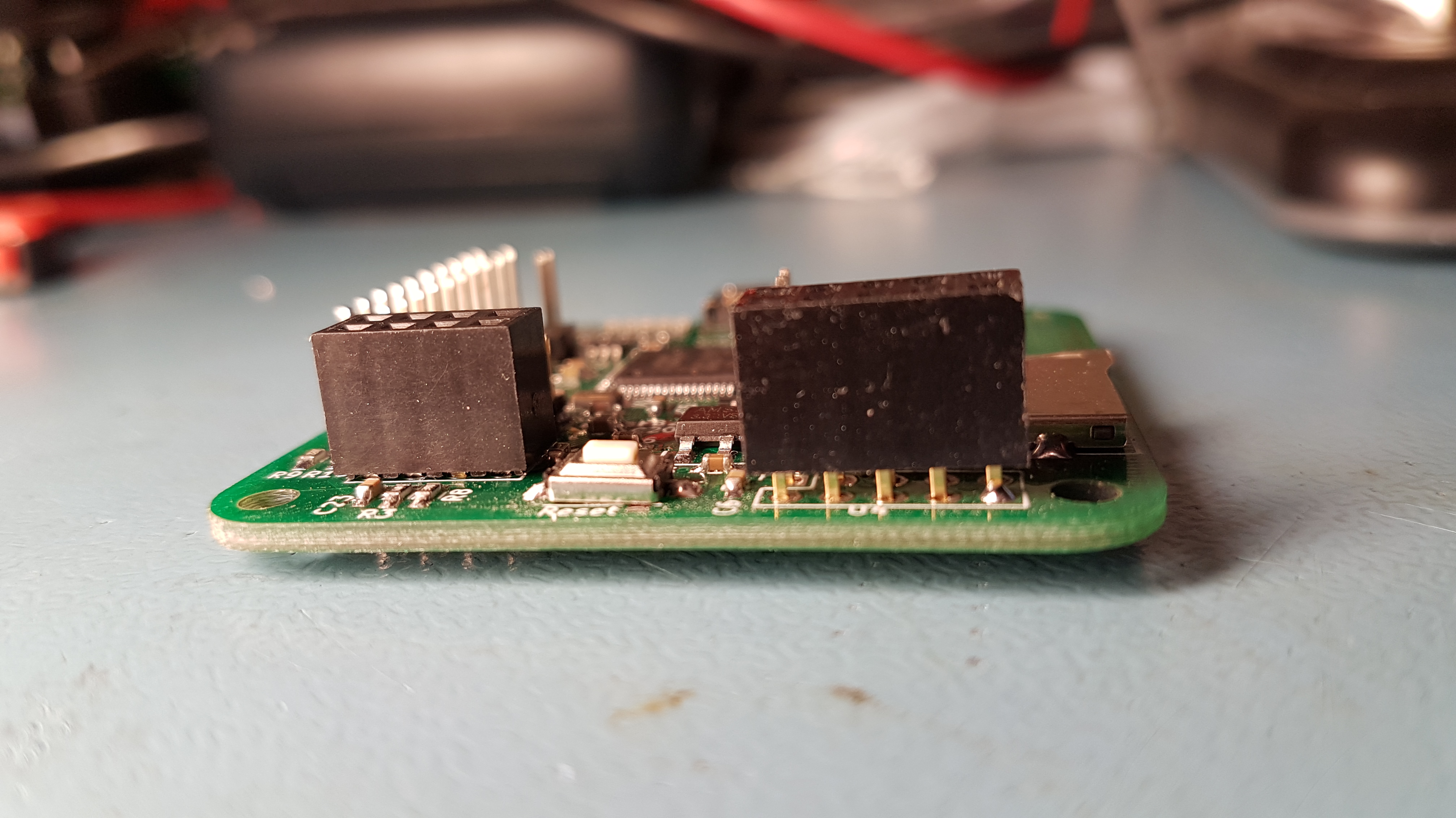
Please note that if you want to use the ethernet module, you need to raise the socket as much as possible above the board while soldering it, as the ethernet jack on board the ethernet module is slightly higher than the pinheaders on the board.
The standard GatewayW5100 example under MySensors in the Arduino IDE, is compatible with the Sensebender Gateway, and can be run without problems.
Battery backup
The Gateway hardware supports a backup battery, which can be connected to the 2 terminals right next to the SD card reader. The absolute maximum battery voltage is 3.6V, anything above this level might damage your board! Currently we do not have any example source code to show you, if you want to add the battery, but there is a couple of pins that can be used to check if battery and/or external supply, is attached, MY_BATT_DETECT and MY_SUPPLY_DETECT, both are analog inputs, and can be used with analogRead() function in Arduino like
int battVolt = analogRead(MY_BAT_DETECT);
int supplyVolt = analogRead(MY_SUPPLY_DETECT);
This can then be used to determine if the software should put the gateway into special powerdown modes etc. if external supply is removed.
LED definitions
The LED's is programmable by using a set of defines, that we have added in the board support package:
- LED_1 / LED_BLUE
- LED_2 / LED_RED
- LED_3 / LED_GREEN
- LED_4 / LED_YELLOW
- LED_5 / LED_ORANGE
Both defines are valid (LED_1 and LED_BLUE).
use it as
pinMode(LED_BLUE, OUTPUT);
digitalWrite(LED_BLUE, HIGH);
Please note that some of the LED's are used in the mysensors core.
Expansion
You can use the MysX expansion port to add new hardware functionality to your gateway, like receiver / transmitters for 433Mhz remote controls etc. The connector is documented in detail here. We have made it easier to use the MysX connector in your sketches, by adding a set of MYSX defines, if you use our board definitions in arduino:
#define MYSX_D1_DFM (00ul)
#define MYSX_D2_DTM (01ul)
#define MYSX_D3_INT (02ul)
#define MYSX_D4_INT (03ul)
#define MYSX_D5_PWM (04ul)
#define MYSX_D6_PWM (05ul)
#define MYSX_D7_SCL (06ul)
#define MYSX_D8_SDA (07ul)
#define MYSX_D9_A3 (08ul)
#define MYSX_D10_A4 (09ul)
#define MYSX_D11_MOSI (10ul)
#define MYSX_D12_MISO (11ul)
#define MYSX_D13_SCK (12ul)
#define MYSX_D14_CS (13ul)
#define MYSX_A1 (14ul)
#define MYSX_A2 (15ul)
#define MYSX_SPI SPI2
To use the serial port in the mysx connector, you should use Serial1 in your sketches, as the default Serial is connected to the USB serial device:
Serial1.begin(9600);
Serial1.println("this is a test using serial port in MysX connector");

Serial.begin(9600); // Dummy baudrate, as it's not used by the usb driver
Serial.println("this is a test using the usb serial device");
On board self diagnosis
The default sketch includes a simple self diagnosis option, that test the onboard peripherals, to invoke this, you need to short SWC1 (solder pads on bottom side) during power on. This will run self diagnosis as stand alone mode, blinking the LED's while testing. If you short SWC2 the board will wait for a serial terminal program to open a connection to the USB device, and then print a self diagnosis report on the terminal.
Enclosures
Scalz on the forum has made a series of enclosures that can be printed on a 3d printer, we have added them in the file list below, choose the one that fits your configuration.
Example Sketch
This is the default sketch shipped with the gateway

/**
* The MySensors Arduino library handles the wireless radio link and protocol
* between your home built sensors/actuators and HA controller of choice.
* The sensors forms a self healing radio network with optional repeaters. Each
* repeater and gateway builds a routing tables in EEPROM which keeps track of the
* network topology allowing messages to be routed to nodes.
*
* Created by Henrik Ekblad <[email protected]>
* Copyright (C) 2013-2026 Sensnology AB
* Full contributor list: https://github.com/mysensors/MySensors/graphs/contributors
*
* Documentation: http://www.mysensors.org
* Support Forum: http://forum.mysensors.org
*
* This program is free software; you can redistribute it and/or
* modify it under the terms of the GNU General Public License
* version 2 as published by the Free Software Foundation.
*
*******************************
*
* DESCRIPTION
* The ArduinoGateway prints data received from sensors on the serial link.
* The gateway accepts input on serial which will be sent out on radio network.
*
* This GW code is designed for Sensebender GateWay / (Arduino Zero variant)
*
* Wire connections (OPTIONAL):
* - Inclusion button should be connected to SW2
*
* LEDs on board (default assignments):
* - Orange: USB RX/TX - Blink when receiving / transmitting on USB CDC device
* - Yellow: RX  - Blink fast on radio message received. In inclusion mode will blink fast only on presentation received
* - Green : TX  - Blink fast on radio message transmitted. In inclusion mode will blink slowly
* - Red   : ERR - Fast blink on error during transmission error or receive crc error
* - Blue  : free - (use with LED_BLUE macro)
*
*/

#define SKETCH_VERSION "0.2"
// Enable debug prints to serial monitor
#define MY_DEBUG

// Enable and select radio type attached
#define MY_RADIO_RF24
//#define MY_RADIO_NRF5_ESB
//#define MY_RADIO_RFM69
//#define MY_RADIO_RFM95
//#define MY_PJON

// Set LOW transmit power level as default, if you have an amplified NRF-module and
// power your radio separately with a good regulator you can turn up PA level.
#define MY_RF24_PA_LEVEL RF24_PA_HIGH

// Enable serial gateway
#define MY_GATEWAY_SERIAL

// Define a lower baud rate for Arduinos running on 8 MHz (Arduino Pro Mini 3.3V & Sensebender)
#if F_CPU == 8000000L
#define MY_BAUD_RATE 38400
#endif

// Enable inclusion mode
#define MY_INCLUSION_MODE_FEATURE
// Enable Inclusion mode button on gateway
#define MY_INCLUSION_BUTTON_FEATURE

// Inverses behavior of inclusion button (if using external pullup)
//#define MY_INCLUSION_BUTTON_EXTERNAL_PULLUP

// Set inclusion mode duration (in seconds)
#define MY_INCLUSION_MODE_DURATION 60
// Digital pin used for inclusion mode button
//#define MY_INCLUSION_MODE_BUTTON_PIN  3

// Set blinking period
#define MY_DEFAULT_LED_BLINK_PERIOD 300

// Inverses the behavior of leds
//#define MY_WITH_LEDS_BLINKING_INVERSE

// Flash leds on rx/tx/err
// Uncomment to override default HW configurations
//#define MY_DEFAULT_ERR_LED_PIN 4  // Error led pin
//#define MY_DEFAULT_RX_LED_PIN  6  // Receive led pin
//#define MY_DEFAULT_TX_LED_PIN  5  // the PCB, on board LED

#include <MySensors.h>
#include <SD.h>
#include <drivers/ATSHA204/ATSHA204.cpp>

Sd2Card card;

#define EEPROM_VERIFICATION_ADDRESS 0x01

static uint8_t num_of_leds = 5;
static uint8_t leds[] = {LED_BLUE, LED_RED, LED_GREEN, LED_YELLOW, LED_ORANGE};

void setup()
{
    // Setup locally attached sensors
}

void presentation()
{
    // Present locally attached sensors
}

void loop()
{
    // Send locally attached sensor data here
}


void preHwInit()
{

    pinMode(MY_SWC1, INPUT_PULLUP);
    pinMode(MY_SWC2, INPUT_PULLUP);
    if (digitalRead(MY_SWC1) && digitalRead(MY_SWC2)) {
        return;
    }

    uint8_t tests = 0;

    for (int i=0; i< num_of_leds; i++) {
        pinMode(leds[i], OUTPUT);
    }
    if (digitalRead(MY_SWC1)) {
        uint8_t led_state = 0;
        while (!Serial) {
            digitalWrite(LED_BLUE, led_state);
            led_state ^= 0x01;
            delay(500);
        } // Wait for USB to be connected, before spewing out data.
    }
    digitalWrite(LED_BLUE, LOW);
    if (Serial) {
        Serial.println("Sensebender GateWay test routine");
        Serial.print("MySensors core version : ");
        Serial.println(MYSENSORS_LIBRARY_VERSION);
        Serial.print("GateWay sketch version : ");
        Serial.println(SKETCH_VERSION);
        Serial.println("----------------------------------");
        Serial.println();
    }
    if (testSha204()) {
        digitalWrite(LED_GREEN, HIGH);
        tests++;
    }
    if (testSDCard()) {
        digitalWrite(LED_YELLOW, HIGH);
        tests++;
    }

    if (testEEProm()) {
        digitalWrite(LED_ORANGE, HIGH);
        tests++;
    }
    if (testAnalog()) {
        digitalWrite(LED_BLUE, HIGH);
        tests++;
    }
    if (tests == 4) {
        while(1) {
            for (int i=0; i<num_of_leds; i++) {
                digitalWrite(leds[i], HIGH);
                delay(200);
                digitalWrite(leds[i], LOW);
            }
        }
    } else {
        while (1) {
            digitalWrite(LED_RED, HIGH);
            delay(200);
            digitalWrite(LED_RED, LOW);
            delay(200);
        }
    }

}

bool testSha204()
{
    uint8_t rx_buffer[SHA204_RSP_SIZE_MAX];
    uint8_t ret_code;
    if (Serial) {
        Serial.print("- > SHA204 ");
    }
    atsha204_init(MY_SIGNING_ATSHA204_PIN);
    ret_code = atsha204_wakeup(rx_buffer);

    if (ret_code == SHA204_SUCCESS) {
        ret_code = atsha204_getSerialNumber(rx_buffer);
        if (ret_code != SHA204_SUCCESS) {
            if (Serial) {
                Serial.println(F("Failed to obtain device serial number. Response: "));
            }
            Serial.println(ret_code, HEX);
        } else {
            if (Serial) {
                Serial.print(F("Ok (serial : "));
                for (int i=0; i<9; i++) {
                    if (rx_buffer[i] < 0x10) {
                        Serial.print('0'); // Because Serial.print does not 0-pad HEX
                    }
                    Serial.print(rx_buffer[i], HEX);
                }
                Serial.println(")");
            }
            return true;
        }
    } else {
        if (Serial) {
            Serial.println(F("Failed to wakeup SHA204"));
        }
    }
    return false;
}

bool testSDCard()
{
    if (Serial) {
        Serial.print("- > SD CARD ");
    }
    if (!card.init(SPI_HALF_SPEED, MY_SDCARD_CS)) {
        if (Serial) {
            Serial.println("SD CARD did not initialize!");
        }
    } else {
        if (Serial) {
            Serial.print("SD Card initialized correct! - ");
            Serial.print("type detected : ");
            switch(card.type()) {
            case SD_CARD_TYPE_SD1:
                Serial.println("SD1");
                break;
            case SD_CARD_TYPE_SD2:
                Serial.println("SD2");
                break;
            case SD_CARD_TYPE_SDHC:
                Serial.println("SDHC");
                break;
            default:
                Serial.println("Unknown");
            }
        }
        return true;
    }
    return false;
}

bool testEEProm()
{
    uint8_t eeprom_d1, eeprom_d2;
    SerialUSB.print(" -> EEPROM ");
    eeprom_d1 = hwReadConfig(EEPROM_VERIFICATION_ADDRESS);
    delay(500);
    eeprom_d1 = ~eeprom_d1; // invert the bits
    hwWriteConfig(EEPROM_VERIFICATION_ADDRESS, eeprom_d1);
    delay(500);
    eeprom_d2 = hwReadConfig(EEPROM_VERIFICATION_ADDRESS);
    if (eeprom_d1 == eeprom_d2) {
        SerialUSB.println("PASSED");
        hwWriteConfig(EEPROM_VERIFICATION_ADDRESS, ~eeprom_d1);
        return true;
    }
    SerialUSB.println("FAILED!");
    return false;
}

bool testAnalog()
{
    int bat_detect = analogRead(MY_BAT_DETECT);
    Serial.print("-> analog : ");
    Serial.print(bat_detect);
    if (bat_detect < 400 || bat_detect > 650) {
        Serial.println(" Failed");
        return false;
    }
    Serial.println(" Passed");
    return true;
}
Appendix A - Installing Windows Drivers
Step 1: Download the driver by right clicking on this link and save it to your computer: mysensors-samd.inf.
Step 2: Open Device Manager as an administrator.

Step 3: Plug in the SenseBender Gateway to your computer, right click on the GW under Other Devices then choose Properties. 
Step 4: On the General tab, click Update Driver 
Step 5: Click "Browse my computer for driver software" 
Step 6: Click "Let me pick from a list of device drivers on my computer" 
Step 7: Choose Ports (COM & LPT) 
Step 8: Click "Have Disk" on the select device driver screen 
Step 9: Browse to the location you downloaded the driver to and open it  
Step 10: After the driver is selected, click Next 
Step 11: Allow the driver to be installed even though it isn't signed  
Step 12: Complete! You should now see the driver was successfully installed.  