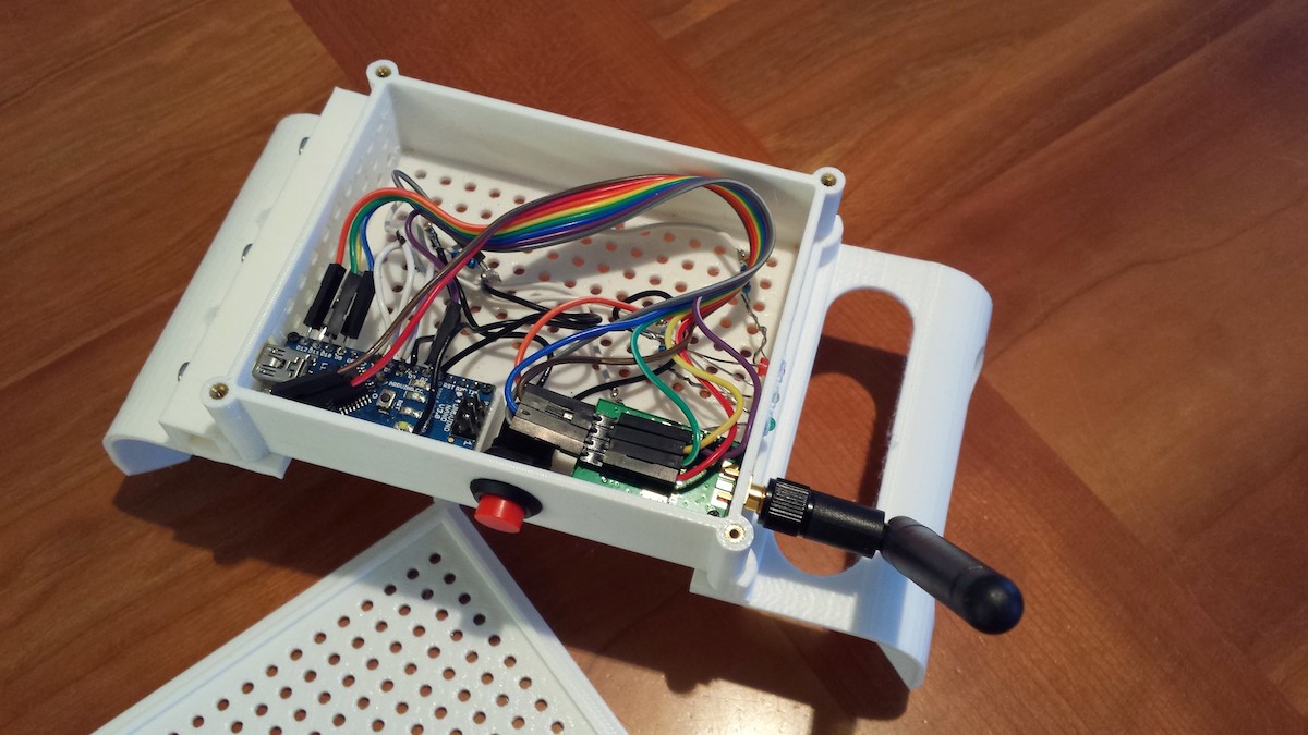
This section is for the enthusiasts that want to pimp their gateway or sensor with some nice extras like activity LEDs and an inclusion mode button.
 ## Inclusion Mode Button
Inclusion mode, is a feature which allows you to inform the controller that you want to add new devices during a short period (60 seconds default) by pressing a physical button on your gateway. Note: This function might not be supported by all the MySensors compatible controllers. To enable this feature in your gateway, set the following defines in your sketch before including MySensors.h.
// Enabled inclusion mode feature
#define MY_INCLUSION_MODE_FEATURE

// Enables inclusion-mode button feature on the gateway device
#define MY_INCLUSION_BUTTON_FEATURE

// Set which pin you have the inclusion button attached to
#define MY_INCLUSION_MODE_BUTTON_PIN 3

// Set inclusion mode duration (in seconds)
#define MY_INCLUSION_MODE_DURATION 60
Connect the push-button momentary-switch between GND and digital pin 3. Note: if using the ESP8266, use pin D1 (GPIO 5) instead of 3
 ## Radio Traffic LEDs
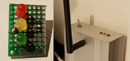
We support three LED feedback signals for radio activity - Read, Transmit, and Error. The Transmit LED is also used to provide visual feedback during active inclusion mode.
| Led color | Arduino Digital Pin | Function |
|---|---|---|
| Green | 6 | Read/RX |
| Yellow | 5 | Transmit/TX |
| Red | 4 | Error/Err |
A good choice would be either a 2 or 3 mm green/yellow/red LEDs. You will also need 3 resistors in the range 270R-510R.
Each LED is connected by its anode (long leg) to +5V. The cathode (short leg) is connected through a resistor to one of the following digital pins of the Arduino:
To enable this feature, set the following defines in your sketch before including MySensors.h.
// Set blinking period (in milliseconds)
#define MY_DEFAULT_LED_BLINK_PERIOD 300

#define MY_DEFAULT_ERR_LED_PIN 4
#define MY_DEFAULT_TX_LED_PIN 5
#define MY_DEFAULT_RX_LED_PIN 6