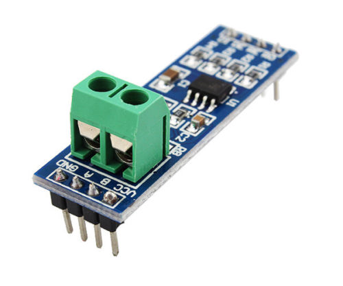
 If you have problems with your steel walls in your home, making radio traffic impossible, you can create a wired MySensors network using RS-485 modules connected to your Arduino.
We're using the AltSoftSerial library (internally) to give the Arduino an additional serial port. This way you can still use pin0/1 for node debug prints.
The AltSoftSerial library can simultaneously transmit and receive. Minimal interference with simultaneous use of HardwareSerial and other libraries. Consumes a 16 bit timer (and will not work with any libraries which need that timer) and disables some PWM pins. Can be sensitive to interrupt usage by other libraries.
Wiring Things Up
| Board | Transmit Pin | Receive Pin | Unusable PWM |
|---|---|---|---|
| Arduino Uno, Duemilanove, LilyPad, Mini (& other ATMEGA328) | 9 | 8 | 10 |
| Arduino Leonardo, Yun, Micro | 5 | 13 | (none) |
| Arduino Mega | 46 | 48 | 44, 45 |
| Teensy 3.0 / 3.1 / 3.2 | 21 | 20 | 22 |
| Teensy 2.0 | 9 | 10 | (none) |
| Teensy++ 2.0 | 25 | 4 | 26, 27 |
You also have to connect the DE-pin output to pin 2 (or some other defined by the MY_RS485_DE_PIN in your sketch).
Demonstration
Example Serial Gateway

/**
* The MySensors Arduino library handles the wireless radio link and protocol
* between your home built sensors/actuators and HA controller of choice.
* The sensors forms a self healing radio network with optional repeaters. Each
* repeater and gateway builds a routing tables in EEPROM which keeps track of the
* network topology allowing messages to be routed to nodes.
*
* Created by Henrik Ekblad <[email protected]>
* Copyright (C) 2013-2019 Sensnology AB
* Full contributor list: https://github.com/mysensors/MySensors/graphs/contributors
*
* Documentation: http://www.mysensors.org
* Support Forum: http://forum.mysensors.org
*
* This program is free software; you can redistribute it and/or
* modify it under the terms of the GNU General Public License
* version 2 as published by the Free Software Foundation.
*
*******************************
*
* DESCRIPTION
* The RS485 Gateway prints data received from sensors on the serial link.
* The gateway accepts input on seral which will be sent out on
* the RS485 link.
*
* Wire connections (OPTIONAL):
* - Inclusion button should be connected between digital pin 3 and GND
* - RX/TX/ERR leds need to be connected between +5V (anode) and digital pin 6/5/4 with resistor 270-330R in a series
*
* LEDs (OPTIONAL):
* - RX (green) - blink fast on radio message received. In inclusion mode will blink fast only on presentation received
* - TX (yellow) - blink fast on radio message transmitted. In inclusion mode will blink slowly
* - ERR (red) - fast blink on error during transmission error or receive crc error
*
* If your Arduino board has additional serial ports
* you can use to connect the RS485 module.
* Otherwise, the gateway uses AltSoftSerial to handle two serial
* links on one Arduino. Use the following pins for RS485 link
*
*  Board          Transmit  Receive   PWM Unusable
* -----          --------  -------   ------------
* Teensy 3.0 & 3.1  21        20         22
* Teensy 2.0         9        10       (none)
* Teensy++ 2.0      25         4       26, 27
* Arduino Uno        9         8         10
* Arduino Leonardo   5        13       (none)
* Arduino Mega      46        48       44, 45
* Wiring-S           5         6          4
* Sanguino          13        14         12
*
*/

// Enable debug prints to serial monitor
#define MY_DEBUG

// Enable RS485 transport layer
#define MY_RS485

// Define this to enables DE-pin management on defined pin
#define MY_RS485_DE_PIN 2

// Set RS485 baud rate to use
#define MY_RS485_BAUD_RATE 9600

// Enable this if RS485 is connected to a hardware serial port
//#define MY_RS485_HWSERIAL Serial1

// Enable serial gateway
#define MY_GATEWAY_SERIAL


// Enable inclusion mode
#define MY_INCLUSION_MODE_FEATURE
// Enable Inclusion mode button on gateway
#define MY_INCLUSION_BUTTON_FEATURE
// Set inclusion mode duration (in seconds)
#define MY_INCLUSION_MODE_DURATION 60
// Digital pin used for inclusion mode button
#define MY_INCLUSION_MODE_BUTTON_PIN  3

// Set blinking period
#define MY_DEFAULT_LED_BLINK_PERIOD 300

// Flash leds on rx/tx/err
#define MY_DEFAULT_ERR_LED_PIN 4  // Error led pin
#define MY_DEFAULT_RX_LED_PIN  5  // Receive led pin
#define MY_DEFAULT_TX_LED_PIN  6  // the PCB, on board LED

#include <MySensors.h>

void setup()
{
    // Setup locally attached sensors
}

void presentation()
{
    // Present locally attached sensors
}

void loop()
{
    // Send locally attached sensor data here
}
Example Motion Sensor
/*
 * The MySensors Arduino library handles the wireless radio link and protocol
 * between your home built sensors/actuators and HA controller of choice.
 * The sensors forms a self healing radio network with optional repeaters. Each
 * repeater and gateway builds a routing tables in EEPROM which keeps track of the
 * network topology allowing messages to be routed to nodes.
 *
 * Created by Henrik Ekblad <[email protected]>
 * Copyright (C) 2013-2019 Sensnology AB
 * Full contributor list: https://github.com/mysensors/MySensors/graphs/contributors
 *
 * Documentation: http://www.mysensors.org
 * Support Forum: http://forum.mysensors.org
 *
 * This program is free software; you can redistribute it and/or
 * modify it under the terms of the GNU General Public License
 * version 2 as published by the Free Software Foundation.
 *
 *******************************
 *
 * REVISION HISTORY
 * Version 1.0 - Henrik Ekblad
 *
 * DESCRIPTION
 * This is an example of sensors using RS485 as transport layer
 *
 * Motion Sensor example using HC-SR501
 * http://www.mysensors.org/build/motion
 *
 * If your Arduino board has additional serial ports
 * you can use to connect the RS485 module.
 * Otherwise, the transport uses AltSoftSerial to handle two serial
 * links on one Arduino. Use the following pins for RS485 link
 *
 *  Board          Transmit  Receive   PWM Unusable
 * -----          --------  -------   ------------
 * Teensy 3.0 & 3.1  21        20         22
 * Teensy 2.0         9        10       (none)
 * Teensy++ 2.0      25         4       26, 27
 * Arduino Uno        9         8         10
 * Arduino Leonardo   5        13       (none)
 * Arduino Mega      46        48       44, 45
 * Wiring-S           5         6          4
 * Sanguino          13        14         12 *
 *
 */

// Enable debug prints to serial monitor
#define MY_DEBUG

// Enable RS485 transport layer
#define MY_RS485

// Define this to enables DE-pin management on defined pin
#define MY_RS485_DE_PIN 2

// Set RS485 baud rate to use
#define MY_RS485_BAUD_RATE 9600

// Enable this if RS485 is connected to a hardware serial port
//#define MY_RS485_HWSERIAL Serial1

#include <MySensors.h>

uint32_t SLEEP_TIME = 120000; // Sleep time between reports (in milliseconds)
#define DIGITAL_INPUT_SENSOR 3   // The digital input you attached your motion sensor.  (Only 2 and 3 generates interrupt!)
#define CHILD_ID 1   // Id of the sensor child

// Initialize motion message
MyMessage msg(CHILD_ID, V_TRIPPED);

void setup()
{
    pinMode(DIGITAL_INPUT_SENSOR, INPUT);      // sets the motion sensor digital pin as input
}

void presentation()
{
    // Send the sketch version information to the gateway and Controller
    sendSketchInfo("Motion Sensor", "1.0");

    // Register all sensors to gw (they will be created as child devices)
    present(CHILD_ID, S_MOTION);
}

void loop()
{
    // Read digital motion value
    bool tripped = digitalRead(DIGITAL_INPUT_SENSOR) == HIGH;

    Serial.println(tripped);
    send(msg.set(tripped?"1":"0"));  // Send tripped value to gw

    // Sleep until interrupt comes in on motion sensor. Send update every two minute.
    sleep(digitalPinToInterrupt(DIGITAL_INPUT_SENSOR), CHANGE, SLEEP_TIME);
}