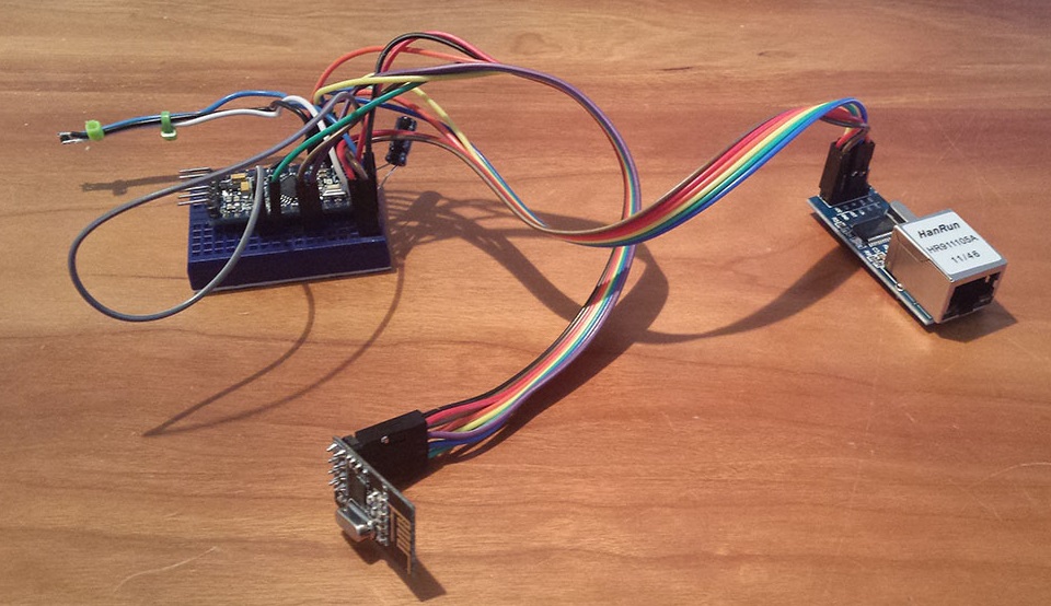
The MQTT gateway is basically a Ethernet Gateway with modified software which makes it act as a MQTT client. Start by building the physical gateway by following ethernet gateway instructions.
The W5100 MQTT gateway sends radio network (or locally attached sensors) data to your MQTT broker. The node also listens to MY_MQTT_TOPIC_PREFIX and sends out those messages to the radio network.
NOTE: No controller supports dynamic ID assignment through MQTT. All nodes must have MY_NODE_ID defined in the sketch to work with MQTT. If you don't set MY_NODE_ID, nodes will complain with the message "!TSM:ID:FAIL".
Configuration
The MQTT gateway sketch contains some static configuration like ip- and port number. Please update these values to fit your needs before uploading it.
// Enable these if your MQTT broker requires usenrame/password
//#define MY_MQTT_USER "username"
//#define MY_MQTT_PASSWORD "password"

// Enable MY_IP_ADDRESS here if you want a static ip address (no DHCP)
#define MY_IP_ADDRESS 192,168,178,87

// If using static ip you need to define Gateway and Subnet address as well
#define MY_IP_GATEWAY_ADDRESS 192,168,178,1
#define MY_IP_SUBNET_ADDRESS 255,255,255,0

// MQTT broker ip address or url. Define one or the other.
//#define MY_CONTROLLER_URL_ADDRESS "m20.cloudmqtt.com"
#define MY_CONTROLLER_IP_ADDRESS 192, 168, 178, 68

// The MQTT broker port to to open
#define MY_PORT 1883
MQTTGateway Example
This is a fully working example sketch.

/*
 * The MySensors Arduino library handles the wireless radio link and protocol
 * between your home built sensors/actuators and HA controller of choice.
 * The sensors forms a self healing radio network with optional repeaters. Each
 * repeater and gateway builds a routing tables in EEPROM which keeps track of the
 * network topology allowing messages to be routed to nodes.
 *
 * Created by Henrik Ekblad <[email protected]>
 * Copyright (C) 2013-2019 Sensnology AB
 * Full contributor list: https://github.com/mysensors/MySensors/graphs/contributors
 *
 * Documentation: http://www.mysensors.org
 * Support Forum: http://forum.mysensors.org
 *
 * This program is free software; you can redistribute it and/or
 * modify it under the terms of the GNU General Public License
 * version 2 as published by the Free Software Foundation.
 *
 *******************************
 *
 * REVISION HISTORY
 * Version 1.0 - Henrik Ekblad
 *
 * DESCRIPTION
 * The W5100 MQTT gateway sends radio network (or locally attached sensors) data to your MQTT broker.
 * The node also listens to MY_MQTT_TOPIC_PREFIX and sends out those messages to the radio network
 *
 * LED purposes:
 * - To use the feature, uncomment WITH_LEDS_BLINKING in MyConfig.h
 * - RX (green) - blink fast on radio message received. In inclusion mode will blink fast only on presentation received
 * - TX (yellow) - blink fast on radio message transmitted. In inclusion mode will blink slowly
 * - ERR (red) - fast blink on error during transmission error or receive crc error
 *
 * See http://www.mysensors.org/build/esp8266_gateway for wiring instructions.
 * nRF24L01+  ESP8266
 * VCC        VCC
 * CE         GPIO4
 * CSN/CS     GPIO15
 * SCK        GPIO14
 * MISO       GPIO12
 * MOSI       GPIO13
 *
 * Not all ESP8266 modules have all pins available on their external interface.
 * This code has been tested on an ESP-12 module.
 * The ESP8266 requires a certain pin configuration to download code, and another one to run code:
 * - Connect REST (reset) via 10K pullup resistor to VCC, and via switch to GND ('reset switch')
 * - Connect GPIO15 via 10K pulldown resistor to GND
 * - Connect CH_PD via 10K resistor to VCC
 * - Connect GPIO2 via 10K resistor to VCC
 * - Connect GPIO0 via 10K resistor to VCC, and via switch to GND ('bootload switch')
 *
  * Inclusion mode button:
 * - Connect GPIO5 via switch to GND ('inclusion switch')
 *
 * Hardware SHA204 signing is currently not supported!
 *
 * Make sure to fill in your ssid and WiFi password below for ssid & pass.
 */


// Enable debug prints to serial monitor
#define MY_DEBUG

// Enables and select radio type (if attached)
#define MY_RADIO_RF24
//#define MY_RADIO_RFM69
//#define MY_RADIO_RFM95

#define MY_GATEWAY_MQTT_CLIENT

// Set this node's subscribe and publish topic prefix
#define MY_MQTT_PUBLISH_TOPIC_PREFIX "mygateway1-out"
#define MY_MQTT_SUBSCRIBE_TOPIC_PREFIX "mygateway1-in"

// Set MQTT client id
#define MY_MQTT_CLIENT_ID "mysensors-1"

// W5100 Ethernet module SPI enable (optional if using a shield/module that manages SPI_EN signal)
//#define MY_W5100_SPI_EN 4

// Enable Soft SPI for NRF radio (note different radio wiring is required)
// The W5100 ethernet module seems to have a hard time co-operate with
// radio on the same spi bus.
#if !defined(MY_W5100_SPI_EN) && !defined(ARDUINO_ARCH_SAMD)
#define MY_SOFTSPI
#define MY_SOFT_SPI_SCK_PIN 14
#define MY_SOFT_SPI_MISO_PIN 16
#define MY_SOFT_SPI_MOSI_PIN 15
#endif

// When W5100 is connected we have to move CE/CSN pins for NRF radio
#ifndef MY_RF24_CE_PIN
#define MY_RF24_CE_PIN 5
#endif
#ifndef MY_RF24_CS_PIN
#define MY_RF24_CS_PIN 6
#endif

// Enable these if your MQTT broker requires username/password
//#define MY_MQTT_USER "username"
//#define MY_MQTT_PASSWORD "password"

// Enable MY_IP_ADDRESS here if you want a static ip address (no DHCP)
#define MY_IP_ADDRESS 192,168,178,87

// If using static ip you can define Gateway and Subnet address as well
//#define MY_IP_GATEWAY_ADDRESS 192,168,178,1
//#define MY_IP_SUBNET_ADDRESS 255,255,255,0

// MQTT broker ip address or url. Define one or the other.
//#define MY_CONTROLLER_URL_ADDRESS "m20.cloudmqtt.com"
#define MY_CONTROLLER_IP_ADDRESS 192, 168, 178, 68

// The MQTT broker port to to open
#define MY_PORT 1883

/*
// Enable inclusion mode
#define MY_INCLUSION_MODE_FEATURE
// Enable Inclusion mode button on gateway
//#define MY_INCLUSION_BUTTON_FEATURE
// Set inclusion mode duration (in seconds)
#define MY_INCLUSION_MODE_DURATION 60
// Digital pin used for inclusion mode button
//#define MY_INCLUSION_MODE_BUTTON_PIN  3

// Set blinking period
#define MY_DEFAULT_LED_BLINK_PERIOD 300

// Flash leds on rx/tx/err
// Uncomment to override default HW configurations
//#define MY_DEFAULT_ERR_LED_PIN 16  // Error led pin
//#define MY_DEFAULT_RX_LED_PIN  16  // Receive led pin
//#define MY_DEFAULT_TX_LED_PIN  16  // the PCB, on board LED
*/

#include <Ethernet.h>
#include <MySensors.h>

void setup()
{
    // Setup locally attached sensors
}

void presentation()
{
    // Present locally attached sensors here
}

void loop()
{
    // Send locally attached sensors data here
}
MQTT Gateway can also be build on a ESP8266 module. Please see comments in MQTTClient.ino code.
/*
 * The MySensors Arduino library handles the wireless radio link and protocol
 * between your home built sensors/actuators and HA controller of choice.
 * The sensors forms a self healing radio network with optional repeaters. Each
 * repeater and gateway builds a routing tables in EEPROM which keeps track of the
 * network topology allowing messages to be routed to nodes.
 *
 * Created by Henrik Ekblad <[email protected]>
 * Copyright (C) 2013-2019 Sensnology AB
 * Full contributor list: https://github.com/mysensors/MySensors/graphs/contributors
 *
 * Documentation: http://www.mysensors.org
 * Support Forum: http://forum.mysensors.org
 *
 * This program is free software; you can redistribute it and/or
 * modify it under the terms of the GNU General Public License
 * version 2 as published by the Free Software Foundation.
 *
 *******************************
 *
 * REVISION HISTORY
 * Version 1.0 - Henrik Ekblad
 *
 * DESCRIPTION
 * The ESP8266 MQTT gateway sends radio network (or locally attached sensors) data to your MQTT broker.
 * The node also listens to MY_MQTT_TOPIC_PREFIX and sends out those messages to the radio network
 *
 * LED purposes:
 * - To use the feature, uncomment any of the MY_DEFAULT_xx_LED_PINs in your sketch
 * - RX (green) - blink fast on radio message received. In inclusion mode will blink fast only on presentation received
 * - TX (yellow) - blink fast on radio message transmitted. In inclusion mode will blink slowly
 * - ERR (red) - fast blink on error during transmission error or receive crc error
 *
 * See https://www.mysensors.org/build/connect_radio for wiring instructions.
 *
 * If you are using a "barebone" ESP8266, see
 * https://www.mysensors.org/build/esp8266_gateway#wiring-for-barebone-esp8266
 *
 * Inclusion mode button:
 * - Connect GPIO5 (=D1) via switch to GND ('inclusion switch')
 *
 * Hardware SHA204 signing is currently not supported!
 *
 * Make sure to fill in your ssid and WiFi password below for ssid & pass.
 */

// Enable debug prints to serial monitor
#define MY_DEBUG

// Use a bit lower baudrate for serial prints on ESP8266 than default in MyConfig.h
#define MY_BAUD_RATE 9600

// Enables and select radio type (if attached)
#define MY_RADIO_RF24
//#define MY_RADIO_RFM69
//#define MY_RADIO_RFM95

#define MY_GATEWAY_MQTT_CLIENT
#define MY_GATEWAY_ESP8266

// Set this node's subscribe and publish topic prefix
#define MY_MQTT_PUBLISH_TOPIC_PREFIX "mygateway1-out"
#define MY_MQTT_SUBSCRIBE_TOPIC_PREFIX "mygateway1-in"

// Set MQTT client id
#define MY_MQTT_CLIENT_ID "mysensors-1"

// Enable these if your MQTT broker requires username/password
//#define MY_MQTT_USER "username"
//#define MY_MQTT_PASSWORD "password"

// Set WIFI SSID and password
#define MY_WIFI_SSID "MySSID"
#define MY_WIFI_PASSWORD "MyVerySecretPassword"

// Set the hostname for the WiFi Client. This is the hostname
// passed to the DHCP server if not static.
#define MY_HOSTNAME "ESP8266_MQTT_GW"

// Enable MY_IP_ADDRESS here if you want a static ip address (no DHCP)
//#define MY_IP_ADDRESS 192,168,178,87

// If using static ip you can define Gateway and Subnet address as well
//#define MY_IP_GATEWAY_ADDRESS 192,168,178,1
//#define MY_IP_SUBNET_ADDRESS 255,255,255,0

// MQTT broker ip address.
#define MY_CONTROLLER_IP_ADDRESS 192, 168, 178, 68

//MQTT broker if using URL instead of ip address.
// #define MY_CONTROLLER_URL_ADDRESS "test.mosquitto.org"

// The MQTT broker port to to open
#define MY_PORT 1883

// Enable inclusion mode
//#define MY_INCLUSION_MODE_FEATURE
// Enable Inclusion mode button on gateway
//#define MY_INCLUSION_BUTTON_FEATURE
// Set inclusion mode duration (in seconds)
//#define MY_INCLUSION_MODE_DURATION 60
// Digital pin used for inclusion mode button
//#define MY_INCLUSION_MODE_BUTTON_PIN D1

// Set blinking period
//#define MY_DEFAULT_LED_BLINK_PERIOD 300

// Flash leds on rx/tx/err
//#define MY_DEFAULT_ERR_LED_PIN 16  // Error led pin
//#define MY_DEFAULT_RX_LED_PIN  16  // Receive led pin
//#define MY_DEFAULT_TX_LED_PIN  16  // the PCB, on board LED

#include <MySensors.h>

void setup()
{
    // Setup locally attached sensors
}

void presentation()
{
    // Present locally attached sensors here
}

void loop()
{
    // Send locally attached sensors data here
}
See Advanced build options for more about inclusion button and leds.
Setup and test gateway
You can run the MQTT gateway on an Arduino+W5100 ethernet module or the ESP8266. Connect radio and ethernet module exactly like for the normal gateway.
The topic resembles the serial protocol. You must define you preferred subscribe and publish prefix in the sketch. The topic is build like this: MY_MQTT_PUBLISH_TOPIC_PREFIX/FROM-NODE-ID/SENSOR-ID/CMD-TYPE/ACK-FLAG/SUB-TYPE
Read more about the serial protocol here. An example topic for data received from your gateway could look like this:
mygateway1-out/2/1/1/0/49
If you want to send data to your sensors use MY_MQTT_SUBSCRIBE_TOPIC_PREFIX defined in your sketch. Should be looking like this (using default sketch):
mygateway1-in/2/1/1/0/49
You can test your gateway using mosquitto as broker.
Make sure to set MY_IP_GATEWAY_ADDRESS in gateway pointing to you computers ip-number (on the same lan).
Start the broker (leave this running):
> mosquitto
Now start your gateway and you should see something like this in the gateway log. Note that I have a GPS sensor running in my radio network which send data to the gateway all the time:
0;0;3;0;9;gateway started, id=0, parent=0, distance=0
0;0;3;0;9;Attempting MQTT connection...
0;0;3;0;9;MQTT connected
0;0;3;0;9;read: 2-2-0 s=1,c=1,t=49,pt=0,l=22,sg=0:55.722519;13.018120
0;0;3;0;9;Sending message on topic: mygateway1-out/2/1/1/0/49
0;0;3;0;9;read: 2-2-0 s=1,c=1,t=49,pt=0,l=22,sg=0:55.722519;13.018121
0;0;3;0;9;Sending message on topic: mygateway1-out/2/1/1/0/49
Subscribe to messages (in another shell on your computer)
> mosquitto_sub -v -t 'mygateway1-out/#'
You should see the messages like you saw in the gateway-log showing up like this:
mygateway1-out/2/1/1/0/49 55.722519;13.018121;13
mygateway1-out/2/1/1/0/49 55.722519;13.018114;12
mygateway1-out/2/1/1/0/49 55.722527;13.018120;11
mygateway1-out/2/1/1/0/49 55.722534;13.018122;10
Sending (publishing) messages to your sensor network:
> mosquitto_pub -t 'mygateway1-in/2/1/1/0/49' -m '0,29'