
Note: The instructions here have been tested and confirmed to work on Orange Pi Zero, it is uncertain whether it will work on other types.
Prepare the system
Install the ARMbian
Download and Install the ARMbian(debian) OS image:
https://www.armbian.com/orange-pi-zero/
Install sunxi-tools
These tools are required to make changes in the boot area of the system:
sudo apt-get update
sudo apt-get install sunxi-tools
Configure spidev
Adding /dev/spidev1.0 is required since /dev/spidev0.0 is used for the onboard NAND flash.
bin2fex /boot/script.bin /tmp/orange.fexNow edit /tmp/orange.fex:
nano /tmp/orange.fexand add/change the following so it looks exactly like the part below:
[spi0]
spi_used = 1
spi_cs_bitmap = 1
spi_mosi = port:PC00<3><default><default><default>
spi_miso = port:PC01<3><default><default><default>
spi_sclk = port:PC02<3><default><default><default>
spi_cs0 = port:PC03<3><1><default><default>

[spi1]
spi_used = 1
spi_cs_bitmap = 1
spi_cs0 = port:PA13<2><1><default><default>
spi_sclk = port:PA14<2><default><default><default>
spi_mosi = port:PA15<2><default><default><default>
spi_miso = port:PA16<2><default><default><default>

[spi_devices]
spi_dev_num = 2

[spi_board0]
modalias = "spidev"
max_speed_hz = 33000000
bus_num = 0
chip_select = 0
mode = 0
full_duplex = 1
manual_cs = 0

[spi_board1]
modalias = "spidev"
max_speed_hz = 33000000
bus_num = 1
chip_select = 0
mode = 0
full_duplex = 1
manual_cs = 0
then recompile the fex file:
sudo fex2bin /tmp/orange.fex /boot/script.binReboot the system:
sudo reboot2 device files should exist now:
$ ls -l /dev/spidev*
crw------- 1 root root 153, 0 Jan 11 16:31 /dev/spidev0.0
crw------- 1 root root 153, 1 Jan 11 16:31 /dev/spidev1.0
Load the gpio module
sudo modprobe gpio-sunxiadd the line gpio-sunxi to /etc/modules to automagically load the module at boot time:
echo "gpio-sunxi" | sudo tee --append /etc/modulesDownload MySensors
Get the code from MySensors repository (development branch):
git clone https://github.com/mysensors/MySensors.git
cd MySensors
Configure
For a complete list of configuration parameters, run:
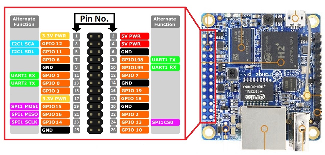
./configure --helpAlways use the GPIO number to set the radio pins. If you follow the connection diagram (see below), pin CE is connected to pin 22, which is GPIO number 2 and CS is connected to pin 24, which is GPIO number 13.
Transport
The transports available are: rf24, rs485, rfm95, rfm69
NRF24
--spi-spidev-device=/dev/spidev1.0 --my-transport=rf24 --my-rf24-ce-pin=2 --my-rf24-cs-pin=13RFM69
--spi-spidev-device=/dev/spidev1.0 --my-transport=rfm69 --my-rfm69-irq-pin=2 --my-rfm69-cs-pin=13 --my-rfm69-frequency=868 --my-is-rfm69hwThe frequency can be set to 315,433,868 or 915 Mhz; --my-is-rfm69hw enables high-powered rfm69hw radios.
Note: The OrangePi uses the new RFM69 driver which is not compatible with the old (=default) RFM69 driver, you need to add #define MY_RFM69_NEW_DRIVER to your nodes to properly communicate with the gateway (available only in development branch).
Gateway type
The types available are: ethernet, serial, mqtt
Ethernet gateway
By default, the gateway is built for ethernet and it listens on port 5003:
--my-gateway=ethernet --my-port=5003To set the gateway as a client that connects to a controller, use:
--my-gateway=ethernet --my-controller-url-address=YOUR-CONTROLLER-ADDRESSor
--my-gateway=ethernet --my-controller-ip-address=YOUR-CONTROLLER-IPSerial gateway
If you are running a controller on the Raspberry Pi that doesn't support communication with the gateway through ethernet, you can use a virtual serial port:
--my-gateway=serial --my-serial-is-pty --my-serial-pty=/dev/ttyMySensorsGatewayFor some controllers a more recognisable name needs to be used: e.g. /dev/ttyUSB020 (check if this is free).
MQTT
The following is an example of how to build a MQTT gateway:
--my-gateway=mqtt --my-controller-ip-address=127.0.0.1 --my-mqtt-publish-topic-prefix=mysensors-out --my-mqtt-subscribe-topic-prefix=mysensors-in --my-mqtt-client-id=mygateway1Build
To build the gateway, run:
makeIf there were no errors during compilation the file bin/mysgw will be created.
Test
The gateway needs root privilege to run, for a list of parameters that can be used, run:
sudo ./bin/mysgw -hThe first time you run the gateway, enable the debug messages to verify that it is working:
sudo ./bin/mysgwThe following message indicates that communication with the nrf24 or rfm69 module failed:
mysgw: Starting gateway...
mysgw: Protocol version - 2.2.0-beta
mysgw: MCO:BGN:INIT GW,CP=RNNG---,VER=2.2.0-beta
mysgw: TSM:INIT
mysgw: TSF:WUR:MS=0
mysgw: !TSM:INIT:TSP FAIL
mysgw: TSM:FAIL:CNT=1
mysgw: TSM:FAIL:PDT
A success message would be:
mysgw: Starting gateway...
mysgw: Protocol version - 2.2.0-beta
mysgw: MCO:BGN:INIT GW,CP=RNNG---,VER=2.2.0-beta
mysgw: TSF:LRT:OK
mysgw: TSM:INIT
mysgw: TSF:WUR:MS=0
mysgw: TSM:INIT:TSP OK
mysgw: TSM:INIT:GW MODE
mysgw: TSM:READY:ID=0,PAR=0,DIS=0
mysgw: MCO:REG:NOT NEEDED
mysgw: Listening for connections on 0.0.0.0:5003
mysgw: MCO:BGN:STP
mysgw: MCO:BGN:INIT OK,TSP=1
Install
To install run:
sudo make installTo start service automatically when the Orange Pie boots:
sudo systemctl enable mysgw.serviceWiring
Oragen Pi Zero
NRF24L01+ Radio
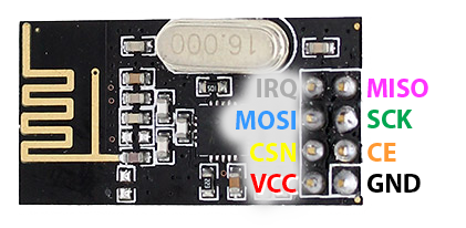
| OrangePi Pin No. | NRF24L01+ | Color |
|---|---|---|
| GND | GND | Black |
| 3.3V | VCC | Red |
| 22 / GPIO2 | CE | Orange |
| 24 / GPIO13 | CSN/CS | Yellow |
| 23 / GPIO14 | SCK | Green |
| 19 / GPIO15 | MOSI | Blue |
| 21 / GPIO16 | MISO | Violet |
| 26 / GPIO10 *()** | IRQ | Gray |
*()**: Optional, more info here.
RFM69 Radio
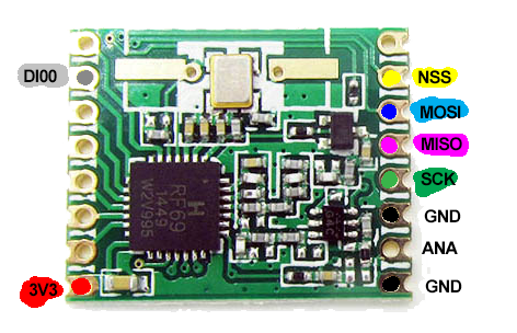
| Raspberry | RFM69 | Color |
|---|---|---|
| GND | GND | Black |
| 3.3V | VCC | Red |
| 24 / GPIO13 | NSS | Yellow |
| 23 / GPIO14 | SCK | Green |
| 19 / GPIO15 | MOSI | Blue |
| 21 / GPIO16 | MISO | Violet |
| 22 / GPIO2 | DI00 | Gray |
| ANA | Antenna* | |
| RST | Not used** |
* Solder a piece of wire, more info here.
** Adafruit modules need RST connected to GND, or to MY_RFM69_RST_PIN
Improving throughput for nrf24
Normally the gateway asks the nrf24 module if a new radio message is available and then sleep a few milliseconds before asking again. This is necessary to avoid high CPU usage. During the gateway sleeping period, the module will still listen for new messages, but if multiple messages arrive, it won't take all.
There is another method were the interrupt pin from the nrf24 modules is used to inform when a new message arrives and it's immediately added to a queue for further processing. To use this method connect the interrupt pin from the nrf24 module to your Orange Pi (check the wiring part for more details) and use the "--my-rf24-irq-pin=PIN" option to configure the gateway.
In the following example, the interrupt pin is connected to the Orange Pi pin 26 / GPIO10:
./configure --spi-spidev-device=/dev/spidev1.0 --my-transport=rf24 --my-rf24-ce-pin=2 --my-rf24-cs-pin=13 --my-rf24-irq-pin=10