
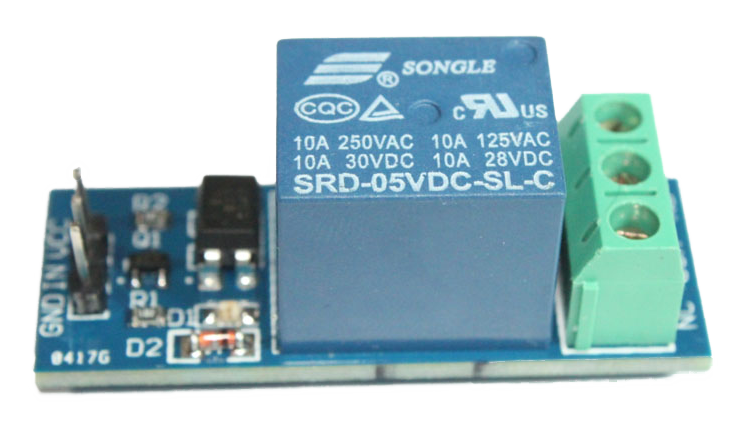
Controlling a relay can be very useful. You can turn lights on and off or why not control your garage door or heater?
You can find relay modules with 1, 2, 4, 8 and more channels. Each relay requires one of your Arduinos digital outputs to control it.
Make sure to power the relay module separately if you use more than one relay. If you try to power the relays directly from the Arduino you will definitely experience restarts and other failures.
You can fine tune how many relays you want to control in the example sketch by modifying the NUMBER_OF_RELAYS parameter. The first relay uses digital out 3, relay number two uses digital out 4 and so on.
When the actuator starts it fetches the last known relay state from the controller.
Demonstration
Here is a video done by the communnity member petewill showing how to build a smart plug module:
There's also a forum thread describing the project.
Wiring Things Up
Start by connecting the radio module.
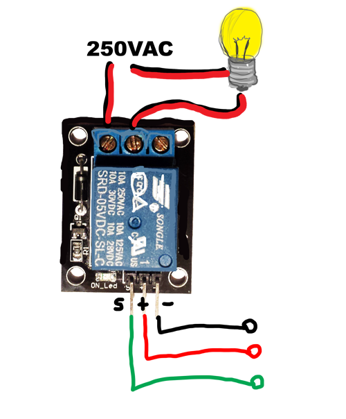
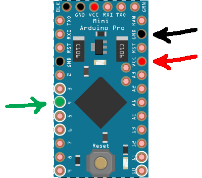
| Relay | Arduino | Comment |
|---|---|---|
| - or GND | GND | Black |
| + or VCC | +5V | Red |
| S or IN | Digital pin 4 (D4) | Green |
Example

/*
 * The MySensors Arduino library handles the wireless radio link and protocol
 * between your home built sensors/actuators and HA controller of choice.
 * The sensors forms a self healing radio network with optional repeaters. Each
 * repeater and gateway builds a routing tables in EEPROM which keeps track of the
 * network topology allowing messages to be routed to nodes.
 *
 * Created by Henrik Ekblad <[email protected]>
 * Copyright (C) 2013-2019 Sensnology AB
 * Full contributor list: https://github.com/mysensors/MySensors/graphs/contributors
 *
 * Documentation: http://www.mysensors.org
 * Support Forum: http://forum.mysensors.org
 *
 * This program is free software; you can redistribute it and/or
 * modify it under the terms of the GNU General Public License
 * version 2 as published by the Free Software Foundation.
 *
 *******************************
 *
 * REVISION HISTORY
 * Version 1.0 - Henrik Ekblad
 *
 * DESCRIPTION
 * Example sketch showing how to control physical relays.
 * This example will remember relay state after power failure.
 * http://www.mysensors.org/build/relay
 */

// Enable debug prints to serial monitor
#define MY_DEBUG

// Enable and select radio type attached
#define MY_RADIO_RF24
//#define MY_RADIO_NRF5_ESB
//#define MY_RADIO_RFM69
//#define MY_RADIO_RFM95

// Enable repeater functionality for this node
#define MY_REPEATER_FEATURE

#include <MySensors.h>

#define RELAY_PIN 4  // Arduino Digital I/O pin number for first relay (second on pin+1 etc)
#define NUMBER_OF_RELAYS 1 // Total number of attached relays
#define RELAY_ON 1  // GPIO value to write to turn on attached relay
#define RELAY_OFF 0 // GPIO value to write to turn off attached relay


void before()
{
    for (int sensor=1, pin=RELAY_PIN; sensor<=NUMBER_OF_RELAYS; sensor++, pin++) {
        // Then set relay pins in output mode
        pinMode(pin, OUTPUT);
        // Set relay to last known state (using eeprom storage)
        digitalWrite(pin, loadState(sensor)?RELAY_ON:RELAY_OFF);
    }
}

void setup()
{

}

void presentation()
{
    // Send the sketch version information to the gateway and Controller
    sendSketchInfo("Relay", "1.0");

    for (int sensor=1, pin=RELAY_PIN; sensor<=NUMBER_OF_RELAYS; sensor++, pin++) {
        // Register all sensors to gw (they will be created as child devices)
        present(sensor, S_BINARY);
    }
}


void loop()
{

}

void receive(const MyMessage &message)
{
    // We only expect one type of message from controller. But we better check anyway.
    if (message.getType()==V_STATUS) {
        // Change relay state
        digitalWrite(message.getSensor()-1+RELAY_PIN, message.getBool()?RELAY_ON:RELAY_OFF);
        // Store state in eeprom
        saveState(message.getSensor(), message.getBool());
        // Write some debug info
        Serial.print("Incoming change for sensor:");
        Serial.print(message.getSensor());
        Serial.print(", New status: ");
        Serial.println(message.getBool());
    }
}
Example with button

/**
 * The MySensors Arduino library handles the wireless radio link and protocol
 * between your home built sensors/actuators and HA controller of choice.
 * The sensors forms a self healing radio network with optional repeaters. Each
 * repeater and gateway builds a routing tables in EEPROM which keeps track of the
 * network topology allowing messages to be routed to nodes.
 *
 * Created by Henrik Ekblad <[email protected]>
 * Copyright (C) 2013-2015 Sensnology AB
 * Full contributor list: https://github.com/mysensors/Arduino/graphs/contributors
 *
 * Documentation: http://www.mysensors.org
 * Support Forum: http://forum.mysensors.org
 *
 * This program is free software; you can redistribute it and/or
 * modify it under the terms of the GNU General Public License
 * version 2 as published by the Free Software Foundation.
 *
 *******************************
 *
 * REVISION HISTORY
 * Version 1.0 - Henrik Ekblad
 *
 * DESCRIPTION
 * Example sketch for a "light switch" where you can control light or something
 * else from both HA controller and a local physical button
 * (connected between digital pin 3 and GND).
 * This node also works as a repeader for other nodes
 * http://www.mysensors.org/build/relay
 */

// Enable debug prints to serial monitor
#define MY_DEBUG

// Enable and select radio type attached
#define MY_RADIO_RF24
//#define MY_RADIO_RFM69

// Enabled repeater feature for this node
#define MY_REPEATER_FEATURE

#include <MySensors.h>
#include <Bounce2.h>

#define RELAY_PIN  4  // Arduino Digital I/O pin number for relay
#define BUTTON_PIN  3  // Arduino Digital I/O pin number for button
#define CHILD_ID 1   // Id of the sensor child
#define RELAY_ON 1
#define RELAY_OFF 0

Bounce debouncer = Bounce();
int oldValue=0;
bool state;

MyMessage msg(CHILD_ID,V_LIGHT);

void setup()
{
  // Setup the button
  pinMode(BUTTON_PIN,INPUT);
  // Activate internal pull-up
  digitalWrite(BUTTON_PIN,HIGH);

  // After setting up the button, setup debouncer
  debouncer.attach(BUTTON_PIN);
  debouncer.interval(5);

  // Make sure relays are off when starting up
  digitalWrite(RELAY_PIN, RELAY_OFF);
  // Then set relay pins in output mode
  pinMode(RELAY_PIN, OUTPUT);

  // Set relay to last known state (using eeprom storage)
  state = loadState(CHILD_ID);
  digitalWrite(RELAY_PIN, state?RELAY_ON:RELAY_OFF);
}

void presentation()  {
  // Send the sketch version information to the gateway and Controller
  sendSketchInfo("Relay & Button", "1.0");

  // Register all sensors to gw (they will be created as child devices)
  present(CHILD_ID, S_LIGHT);
}

/*
*  Example on how to asynchronously check for new messages from gw
*/
void loop()
{
  debouncer.update();
  // Get the update value
  int value = debouncer.read();
  if (value != oldValue && value==0) {
      send(msg.set(state?false:true), true); // Send new state and request ack back
  }
  oldValue = value;
}

void receive(const MyMessage &message) {
  // We only expect one type of message from controller. But we better check anyway.
  if (message.isAck()) {
     Serial.println("This is an ack from gateway");
  }

  if (message.type == V_LIGHT) {
     // Change relay state
     state = message.getBool();
     digitalWrite(RELAY_PIN, state?RELAY_ON:RELAY_OFF);
     // Store state in eeprom
     saveState(CHILD_ID, state);

     // Write some debug info
     Serial.print("Incoming change for sensor:");
     Serial.print(message.sensor);
     Serial.print(", New status: ");
     Serial.println(message.getBool());
   }
}