
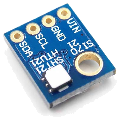
 The Si7021 humidity and temperature sensor is a modern & accurate sensor, readily available on small breakout boards. It is a better alternative to the [DHT](/build/humidity) sensors, and uses less power.
It contains an optional protective white cover, which shields the sensor for dust and dirt (as shown in the picture).
Compatible sensor variants exist (HTU21D, SHT21, Si7020), which share their software implementation.
The Si7021 humidity and temperature sensor is a modern & accurate sensor, readily available on small breakout boards. It is a better alternative to the [DHT](/build/humidity) sensors, and uses less power.
It contains an optional protective white cover, which shields the sensor for dust and dirt (as shown in the picture).
Compatible sensor variants exist (HTU21D, SHT21, Si7020), which share their software implementation.
See this comparison for in-depth information on accuracy of different sensors.
Wiring Things Up
Start by connecting the radio module.
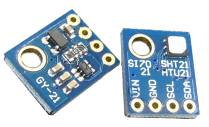
The native sensor's operating range is 1.9 to 3.6V. Therefore two common variants of breakout boards can be found on the internet: one containing its own voltage regulator and level conversion to make it compatible with 5V Arduino's, and another variant that lacks a voltage regulator and level conversion making it **only **compatible with 3.3V Arduino's.
The 5V compatible modules are often marked 'GY-21' and can be identified by the extra components on the bottom of their circuit board. Examples of 5V Arduinos's are Uno, Nano and Pro Mini 5V.
| 5V Sensor | Arduino |
|---|---|
| GND | GND |
| VIN | VCC or 5V |
| SDA | A4 |
| SCL | A5 |
The SCL & SDA pins mentioned are available at A5 & A4 on Arduino Uno, Nano and Pro Mini. Other boards use different mappings, see here.
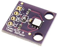
The 3.3V compatible modules usually contain no extra components on the bottom of their circuit board, and seem to be knowns also as 'GY-213v'. An example of a 3.3V Arduino is the Pro Mini 3.3V.
| 3.3V Sensor | Arduino |
|---|---|
| GND or - | GND |
| 3.3V or + | VCC or 3.3V |
| SDA or DA | A4 |
| SCL or CL | A5 |
Example
This example uses the Si7021 library, which is included in the MySensors external examples. If you choose to report battery level to the gateway (by defining REPORT_BATTERY_LEVEL at the top of the sketch) the Vcc library is also required. Please install the librarie(s) and restart the Arduino IDE before trying to compile.

/**
 * The MySensors Arduino library handles the wireless radio link and protocol
 * between your home built sensors/actuators and HA controller of choice.
 * The sensors forms a self healing radio network with optional repeaters. Each
 * repeater and gateway builds a routing tables in EEPROM which keeps track of the
 * network topology allowing messages to be routed to nodes.
 *
 * Created by Henrik Ekblad <[email protected]>
 * Copyright (C) 2013-2015 Sensnology AB
 * Full contributor list: https://github.com/mysensors/Arduino/graphs/contributors
 *
 * Documentation: http://www.mysensors.org
 * Support Forum: http://forum.mysensors.org
 *
 * This program is free software; you can redistribute it and/or
 * modify it under the terms of the GNU General Public License
 * version 2 as published by the Free Software Foundation.
 *
 *******************************
 *
 * REVISION HISTORY
 * Version 1.0: Yveaux
 *
 * DESCRIPTION
 * This sketch provides an example of how to implement a humidity/temperature
 * sensor using a Si7021 sensor.
 *
 * For more information, please visit:
 * http://www.mysensors.org/build/humiditySi7021
 *
 */

// Enable debug prints
#define MY_DEBUG

// Enable REPORT_BATTERY_LEVEL to measure battery level and send changes to gateway
//#define REPORT_BATTERY_LEVEL

// Enable and select radio type attached
#define MY_RADIO_RF24
//#define MY_RADIO_RFM69
//#define MY_RS485

#include <MySensors.h>

#define CHILD_ID_HUM  0
#define CHILD_ID_TEMP 1

static bool metric = true;

// Sleep time between sensor updates (in milliseconds)
static const uint64_t UPDATE_INTERVAL = 60000;

#include <SI7021.h>
static SI7021 sensor;

#ifdef REPORT_BATTERY_LEVEL
#include <Vcc.h>
static uint8_t oldBatteryPcnt = 200;  // Initialize to 200 to assure first time value will be sent.
const float VccMin        = 1.8;      // Minimum expected Vcc level, in Volts: Brownout at 1.8V    -> 0%
const float VccMax        = 2.0*1.6;  // Maximum expected Vcc level, in Volts: 2xAA fresh Alkaline -> 100%
const float VccCorrection = 1.0;      // Measured Vcc by multimeter divided by reported Vcc
static Vcc vcc(VccCorrection);
#endif

void presentation()
{
  // Send the sketch info to the gateway
  sendSketchInfo("TemperatureAndHumidity", "1.0");

  // Present sensors as children to gateway
  present(CHILD_ID_HUM, S_HUM,   "Humidity");
  present(CHILD_ID_TEMP, S_TEMP, "Temperature");

  metric = getControllerConfig().isMetric;
}

void setup()
{
  while (not sensor.begin())
  {
    Serial.println(F("Sensor not detected!"));
    delay(5000);
  }
}


void loop()
{
  // Read temperature & humidity from sensor.
  const float temperature = float( metric ? sensor.getCelsiusHundredths() : sensor.getFahrenheitHundredths() ) / 100.0;
  const float humidity    = float( sensor.getHumidityBasisPoints() ) / 100.0;

#ifdef MY_DEBUG
  Serial.print(F("Temp "));
  Serial.print(temperature);
  Serial.print(metric ? 'C' : 'F');
  Serial.print(F("\tHum "));
  Serial.println(humidity);
#endif

  static MyMessage msgHum( CHILD_ID_HUM,  V_HUM );
  static MyMessage msgTemp(CHILD_ID_TEMP, V_TEMP);

  send(msgTemp.set(temperature, 2));
  send(msgHum.set(humidity, 2));

#ifdef REPORT_BATTERY_LEVEL
  const uint8_t batteryPcnt = static_cast<uint8_t>(0.5 + vcc.Read_Perc(VccMin, VccMax));

#ifdef MY_DEBUG
  Serial.print(F("Vbat "));
  Serial.print(vcc.Read_Volts());
  Serial.print(F("\tPerc "));
  Serial.println(batteryPcnt);
#endif

  // Battery readout should only go down. So report only when new value is smaller than previous one.
  if ( batteryPcnt < oldBatteryPcnt )
  {
      sendBatteryLevel(batteryPcnt);
      oldBatteryPcnt = batteryPcnt;
  }
#endif

  // Sleep until next update to save energy
  sleep(UPDATE_INTERVAL);
}
Battery powering
This sensor can be turned into a 2xAA battery powered sensor. Start with 3.3V Pro Mini, optimized for battery powering. Measurement of the remaining battery life can simply be enabled by defining REPORT_BATTERY_LEVEL at the top of the sketch, which does not require two resisors as described here. Choose the 3.3V Si7021 sensor described above, as the Pro Mini runs on 3.3V.
Images
Datasheets
| Name | Size | # Downloads |
|---|---|---|
| Si7021-A20.pdf | 1.56 MB | 2665 |